Drum housing for a working drum of a construction machine or mining machine, construction machine or mining machine, as well as method for monitoring the condition of a working drum of a construction machine or mining machine

a technology for mining machines and working drums, which is applied in the direction of maintenance of machinability, ways, roads, etc., can solve the problems of ongoing process, loss of efficiency, and wear and tear of the working drum, and achieve the effect of reducing the time of inspection

Active Publication Date: 2015-11-03
WIRTGEN GMBH
View PDF41 Cites 20 Cited by
  • Summary
  • Abstract
  • Description
  • Claims
  • Application Information

AI Technical Summary

Benefits of technology

[0012]It is therefore the object of the invention to create a drum housing, a construction machine or mining machine, as well as a method for monitoring the condition of a working drum in which a monitoring device can be used at any time without any mounting effort and allows economy of time in the inspection of working drums.

Problems solved by technology

The working drum of a construction machine, which is provided with tools and rotates about a drum axis, such as a milling drum during the working of road surfaces by means of road milling machines, as well as for the mining of deposits by means of surface miners, is subject to a continuous process of wear and tear, wherein a tool breakage may also occur.
When the tools reach a certain state of wear, it is advisable to replace the tools as the ongoing process will otherwise lose in efficiency.
1. Replacement of the milling tool as there is no longer sufficient wear material, especially carbide metal in the tip. The penetration resistance becomes too great, which leads to the efficiency decreasing as a result of excessive friction loss. Wear and tear is mainly rotationally symmetrical.
2. Replacement of the toolholder as between the milling tool and holder, at the contact surface between these parts, wear and tear in particular of the holder occurs and the wear limit has been reached. This type of wear and tear is usually symmetrical.
3. Non-rotationally symmetrical wear and tear of the milling tool tip and / or the milling tool head caused by insufficient rotational movement of the milling tool during the milling process. This results in a poor milling pattern and the risk of a tool breakage as the supporting effect of the milling tool head is lost.
4. Furthermore, the toolholder may be subject to additional, non-rotationally symmetrical wear and tear.
5. Milling tool breakage.
Furthermore, worn-out and / or broken milling tools can result in secondary damage to the toolholders, or worn-out toolholders, respectively, can result in secondary damage to the milling drum.
Replacing the milling tools and / or toolholders too early, on the other hand, also means not working at optimal cost.
In such a case, existing wear potential is not utilized appropriately.
Checking the state of wear of the milling tool and holder is very time-consuming and reduces the operating time of the machine.
In addition, there is the risk, owing to the highly subjective assessment, that the state of wear of the holder and milling tool is not assessed correctly and the wear potential is therefore not optimally utilized.
Owing to the circulating milled material, the barrel inside the drum housing is subject to a high degree of wear and tear and may be severely damaged by larger fragments of the milled material.
Furthermore, damage to the optics of the camera through the barrel cannot be excluded if the camera is not demounted during the milling operation.
The replacement of damaged parts is time-consuming.
In addition, mounting time is incurred by the stowing, or mounting respectively, of the monitoring device.

Method used


Image

  • Drum housing for a working drum of a construction machine or mining machine, construction machine or mining machine, as well as method for monitoring the condition of a working drum of a construction machine or mining machine
  • Drum housing for a working drum of a construction machine or mining machine, construction machine or mining machine, as well as method for monitoring the condition of a working drum of a construction machine or mining machine
  • Drum housing for a working drum of a construction machine or mining machine, construction machine or mining machine, as well as method for monitoring the condition of a working drum of a construction machine or mining machine

Examples


Embodiment Construction

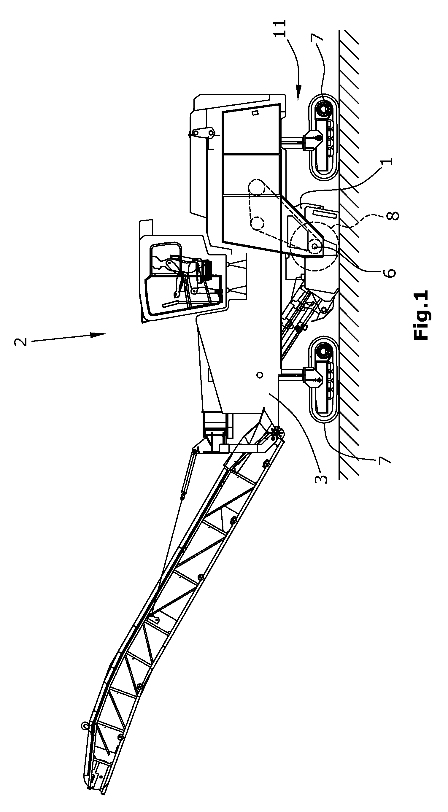
[0043]FIG. 1 shows an example of a construction machine 2 in the design of a road milling machine for milling ground surfaces or traffic surfaces. The road milling machine comprises a chassis with, for example, four crawler track units 7, which supports the machine frame 3 of the road milling machine. It is understood that the crawler track units 7 may be substituted wholly or in part by wheel units. A working drum 8 rotating about a drum axis 6 is supported in the machine frame 3 in the design of a milling drum fitted with tools 4, said milling drum extending transversely to the direction of travel of the construction machine 2. The working drum 8 is partially enclosed by a drum housing 1. Setting of the milling depth is preferably effected by means of the height adjustment of the crawler track units 7 via lifting columns 11 but may also be effected by a height-adjustable working drum 8 in a height-adjustable drum housing 1.

[0044]It is understood that the construction machine 2 wit...


PUM


Abstract

In a drum housing for a working drum of a construction machine or mining machine, the working drum being provided with tools and rotating about a drum axis, with a housing shell which at least partially encloses the circumference of the working drum, and with at least one inspection opening for a monitoring device arranged in the housing shell, wherein the monitoring device inspects the condition of the working drum or the tools thereof, it is provided for the following features to be achieved: a closing mechanism is arranged on the outside of the housing shell, the closing mechanism enabling closure of the at least one inspection opening.

Description

CROSS-REFERENCE TO RELATED APPLICATIONS[0001]The present invention claims the priority of German Patent Application no. DE 10 2011 016 271.2 filed on Apr. 6, 2011, the disclosures of which are incorporated herein by reference.BACKGROUND OF THE INVENTION[0002]1. Field of the Invention[0003]The invention relates to a drum housing for a working drum of a construction machine or mining machine, said working drum being provided with tools and rotating about a drum axis with a specified rotating direction, a construction machine or mining machine with such drum housing, as well as a method for monitoring the condition of a working drum of a construction machine / mining machine or of the tools thereof arranged on the circumference of the working drum by measuring the condition of the working drum or the tools thereof by means of a monitoring device.[0004]2. Description of the Prior Art[0005]Such a method is known from DE 10 2008 045 470 A1 (US 2010 / 0076697). A monitoring device monitors the...

Claims


Application Information

Patent Timeline
Patent Type & Authority Patents(United States)
IPC IPC(8): E01C23/088
CPCE01C23/088E01C23/12G01N3/58G01N3/56E21C25/10E21C35/00
Inventor VON SCHOENEBECK, WINFRIEDBERGES, JOERGBERGHOFF, PETERWAGNER, STEFANBARLMANI, CYRUSHAHN, GUNTER
Owner WIRTGEN GMBH
Why Eureka
Try Eureka