Method and circuit arrangement for checking the rotor position of a synchronous machine

a synchronous machine and rotor position technology, applied in the direction of electronic commutators, starter arrangements, instruments, etc., can solve the problems of failure to reliably detect defective sensors, motor damage, motor control system, etc., to achieve limited electromagnetic or acoustic interference, low wear, and high degree of efficiency

Active Publication Date: 2015-11-10
CONTINENTAL TEVES AG & CO OHG
View PDF17 Cites 2 Cited by
  • Summary
  • Abstract
  • Description
  • Claims
  • Application Information

AI Technical Summary

Benefits of technology

[0011]It is advantageous if the association between the current rotor position and the voltage vector to be applied for the achievement of a desired rotation is determined by means of a specified first commutation scheme. In a specified commutation scheme, rotation through a specific angle may be achieved to an accuracy which is determined by the arrangement and number of sensors, by the application of a voltage vector which differs from the commutation table by an angle-related number of columns.
[0013]During the determination of the rotor position, the currents flowing in the phase windings are subject to appropriate limitation on the basis of temperature information. Specifically, in case of a higher temperature, a higher limiting current is selected and, in case of a lower temperature, a lower limiting current is selected. At a higher temperature, the reduced magnetization of the permanently-excited rotor is offset by a correspondingly increased current flow in the stator windings. The coil currents may be selected to a sufficiently high rating to permit the execution of the method according to the invention. As a result of the limited torque delivered, the risk of any damage to the motor or the driven device is minimal.
[0014]During the determination of the rotor position, it is advantageous if the currents flowing in the phase windings are limited by the alternating cut-in and cut-out of the voltages applied to the phase windings. This permits current limitation, even where the control electronics of the motor include no provision for pulse-width modulation.
[0018]In a particularly preferred arrangement, the electronically-commutated synchronous machine is provided with a permanently-excited rotor and a stator which is provided with three phase windings, together with three rotor position sensors in an appropriate arrangement for a commutation scheme. Prior to the initial determination of a rotor position, a base voltage vector for the commutation scheme is applied, the rotor position is determined by the read-out of data from the position sensors, the appropriate voltage vector is varied in relation to the base voltage vector by specific increments, and the second determination of the rotor position, together with the adjustment of the appropriate voltage vector, are continued progressively until an adjoining rotor position is indicated. This method permits the more accurate determination of the rotor position or of the switchover point of the rotor position sensors.
[0022]In a particularly preferred arrangement, the appropriate voltage vectors are set by the use of known vector modulation methods, whereby dead-time effects in particular are compensated by the appropriate adjustment of the relevant pulse duty factor. Dead-time effects are generated by the requisite time delay associated with the connection of a rectifier bridge, in order to prevent any short-circuit. By the adaptation of the pulse duty factor, i.e. the ratio of the pulse width to the pulse interval, the generation of a voltage vector with a defective angle can be avoided.

Problems solved by technology

Although this method permits the elimination of minor angle errors, it does not permit the reliable detection of a defective sensor.
If the rotor position detected by the sensors is not consistent with the actual rotor position, malfunctions of various types may ensue.
In many cases, this may result in damage to the motor, the driven device or the motor control system.
During the determination of the rotor position, the currents flowing in the phase windings are subject to appropriate limitation on the basis of temperature information.
This permits current limitation, even where the control electronics of the motor include no provision for pulse-width modulation.
In a particularly preferred arrangement, current limitation is achieved by the limitation of the voltage applied, specifically by means of pulse width modulation in the control circuit.

Method used


Image

  • Method and circuit arrangement for checking the rotor position of a synchronous machine
  • Method and circuit arrangement for checking the rotor position of a synchronous machine
  • Method and circuit arrangement for checking the rotor position of a synchronous machine

Examples


Embodiment Construction

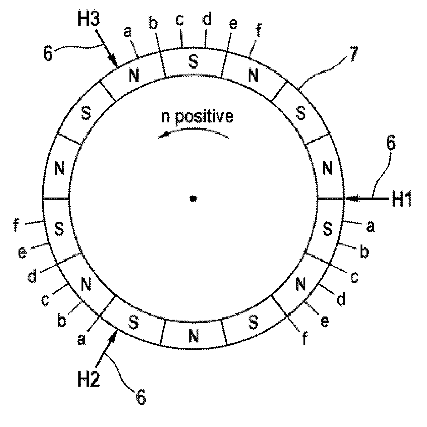
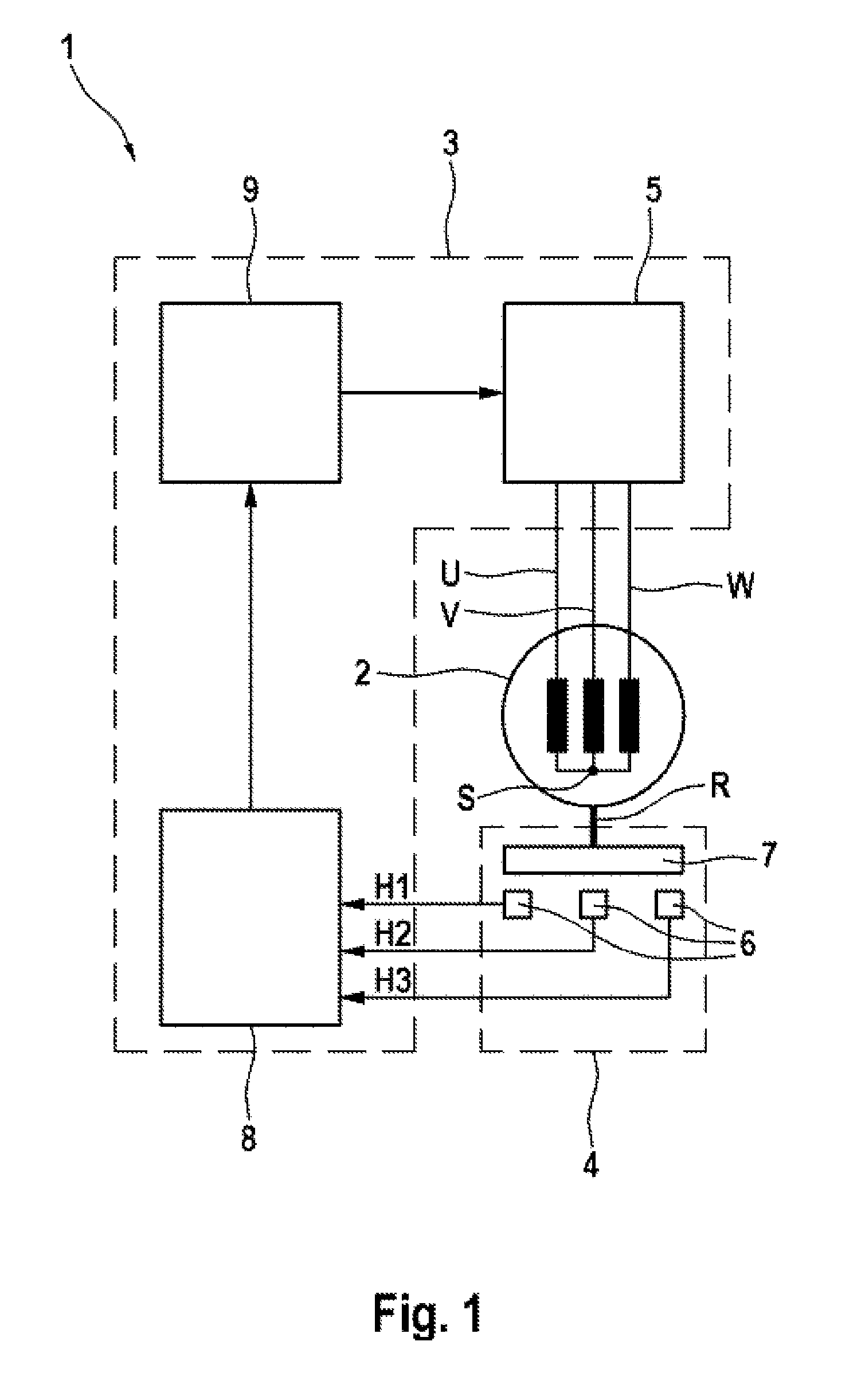
[0036]As represented in FIG. 1, an electronically-commutated synchronous machine 1 comprises an electromechanical energy converter 2, an electronic control device 3 and a rotor position sensor system 4. In addition to the use thereof as a drive mechanism, operation as a generator is also possible, whereby mechanical motion is converted into electrical energy accordingly. The stator is typically comprised of three phase windings, designated as U, V and W, which meet at a star point S. In principle, the delta connection of the phase windings would also be possible. The permanently-excited rotor is connected to a magnetic rotary encoder 7 via a bearing-mounted rotor shaft R. The magnetic field of the rotary encoder is scanned by digital Hall sensors 6. These sensors 6 will be enabled e.g. when they are located in the field of a magnetic north pole, and will conduct no current when a magnetic south pole is in the immediate vicinity. Hall switches of this type have a hysteresis, as a res...


PUM


Abstract

An electronically-commutated synchronous system and method includes a permanently-excited rotor and a stator which is provided with three phase windings, together with three rotor position sensors in an appropriate arrangement for a first commutation scheme. The rotor position is determined by the read-out of data from the position sensors. The appropriate voltage vector is defined by a second commutation scheme, and the second rotor position thus determined is compared with the first commutation scheme. If the rotor position sensors are operating correctly, the position of the rotor may be determined to an accuracy which is equivalent to the interval between two columns in the commutation table.

Description

CROSS-REFERENCE TO RELATED APPLICATIONS[0001]This application claims priority to European Patent Application No. 10464007.3, filed Aug. 5, 2010 and PCT / EP2011 / 063055, filed Jul. 28, 2011.FIELD OF THE INVENTION[0002]The invention relates to a method and to a circuit arrangement for checking the rotor position of a synchronous machine.BACKGROUND AND SUMMARY OF THE INVENTION[0003]Electronically-commutated synchronous machines with a permanently-excited rotor and a stator provided with phase windings, also known as brushless dc motors, enjoy great popularity. They are characterized by low wear, and by their limited electromagnetic or acoustic interference, and show a high degree of efficiency. The influx of current to typically three stator windings generates a magnetic field, in which the permanently-excited rotor in arranged. By the appropriate switchover (commutation) of the currents flowing in the stator windings (or of voltages applied), a rotary motion is generated. Electronically...

Claims


Application Information

Patent Timeline
Patent Type & Authority Patents(United States)
IPC IPC(8): G01B7/14H02P6/22H02P6/18
CPCG01B7/14H02P6/185H02P6/22
Inventor KAUFMANN, TOMSTAUDER, PETERBITSCH, CHRISTIANBUDIANU, BOGDANLEIDECK, JOCHEN
Owner CONTINENTAL TEVES AG & CO OHG
Why Eureka
Try Eureka