Thermally activated magnetic and resistive aging

a technology of resistive aging and magnetic field, which is applied in the direction of instruments, testing dairy products, testing food, etc., can solve the problems of not being able to account for variations in temperature or other ambient conditions during the lifetime, and achieve the reduction of the magnetic field of solid-state materials, the effect of reducing the electrical resistance of solid-state structures and aging properties

Active Publication Date: 2012-10-18
INDIANA UNIVERSITY OF PENNSYLVANIA
View PDF18 Cites 1 Cited by
  • Summary
  • Abstract
  • Description
  • Claims
  • Application Information

AI Technical Summary

Benefits of technology

[0006]Typically, the physical property changes faster with time as the temperature increases. Hence, aging properties of items can be evaluated in a more accurate manner than using a simple timing mechanism. For example, in some aspects, a solid-state structure used as an aging sensor has an electrical resistance (or resistivity) that changes as a function of both time and temperature, providing an indication of aging in an associated item.
[0007]In some examples, nanoparticles, such as nanoflakes, of a first material, such as a ferromagnetic material, are supported within a matrix, such as a semi-metal or semiconducting matrix. Preferably, the matrix material has an electrical conductivity significantly less than the nanoparticle material. In some examples, morphological changes occur within the sensor material, causing an appreciable change in electrical conductivity. Nanostructures may melt and interact with each other to form nanowires of the first material within the matrix material. The electrical conductivity falls appreciably as nanowire networks form through the matrix material, and this may be detected using a pair electrodes. Morphological changes may reduce the magnetization of the solid-state material, which can be detected using a GMR (giant magnetoresistance) sensor.
[0008]In some examples, the first material may be a metal, such as a ferromagnetic metal. The matrix material may be a metal, semimetal, semiconductor, or insulator. Morphological changes in nanostructures of the first material reduce the electrical resistance of the solid-state structure, due to at least partial melting of the first material and formation of nanowires of the first material, during aging.

Problems solved by technology

However, this fails to account for variations in temperature or other ambient conditions during the lifetime.

Method used


Image

  • Thermally activated magnetic and resistive aging
  • Thermally activated magnetic and resistive aging
  • Thermally activated magnetic and resistive aging

Examples


example aging

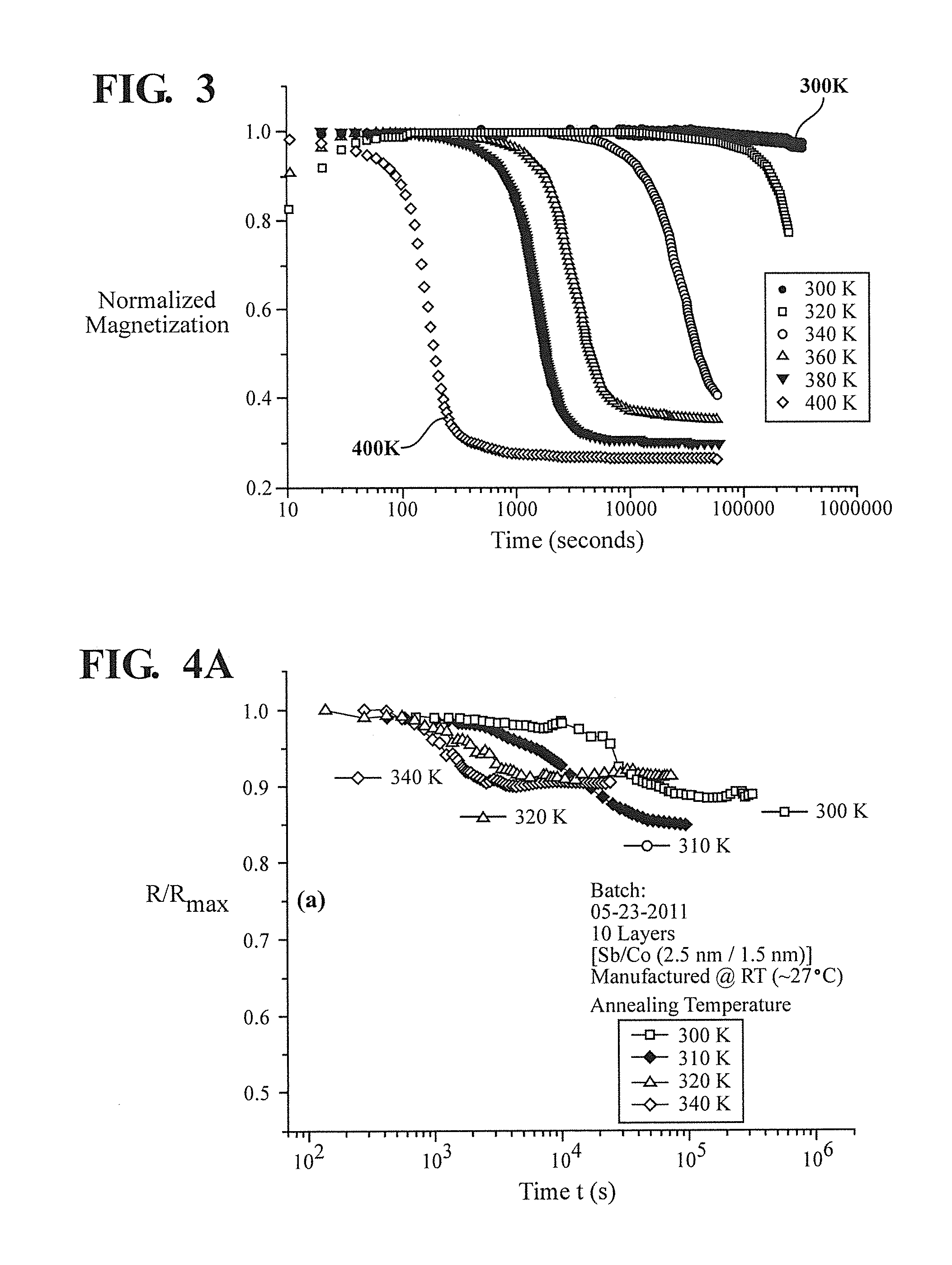
[0115 sensors include a solid-state structure that can be used to mimic, and hence determine, the aging properties of products, systems, and materials such as food items including dairy products, medical supplies, medical monitoring, chemicals (e.g. volatile chemicals), pathogen (e.g. bacterial) growth, electronic circuits such as semiconductor devices, mechanical components, structural components, materials, and the like. In some examples, the faster aging of hotter items can be monitored and determined using the electrical resistance and / or magnetization of a solid-state device. Other parameters, such as thermal resistance, specific heat, etc. may also be monitored. A distinct change in one or more parameters may be observed representing aging of the item of interest.

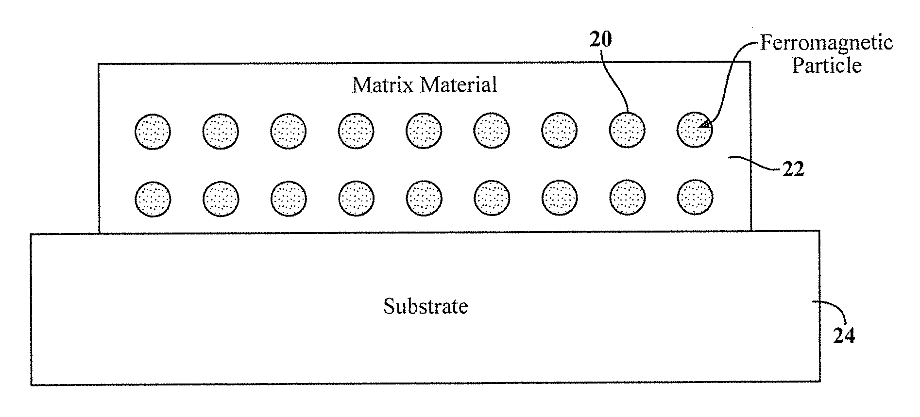
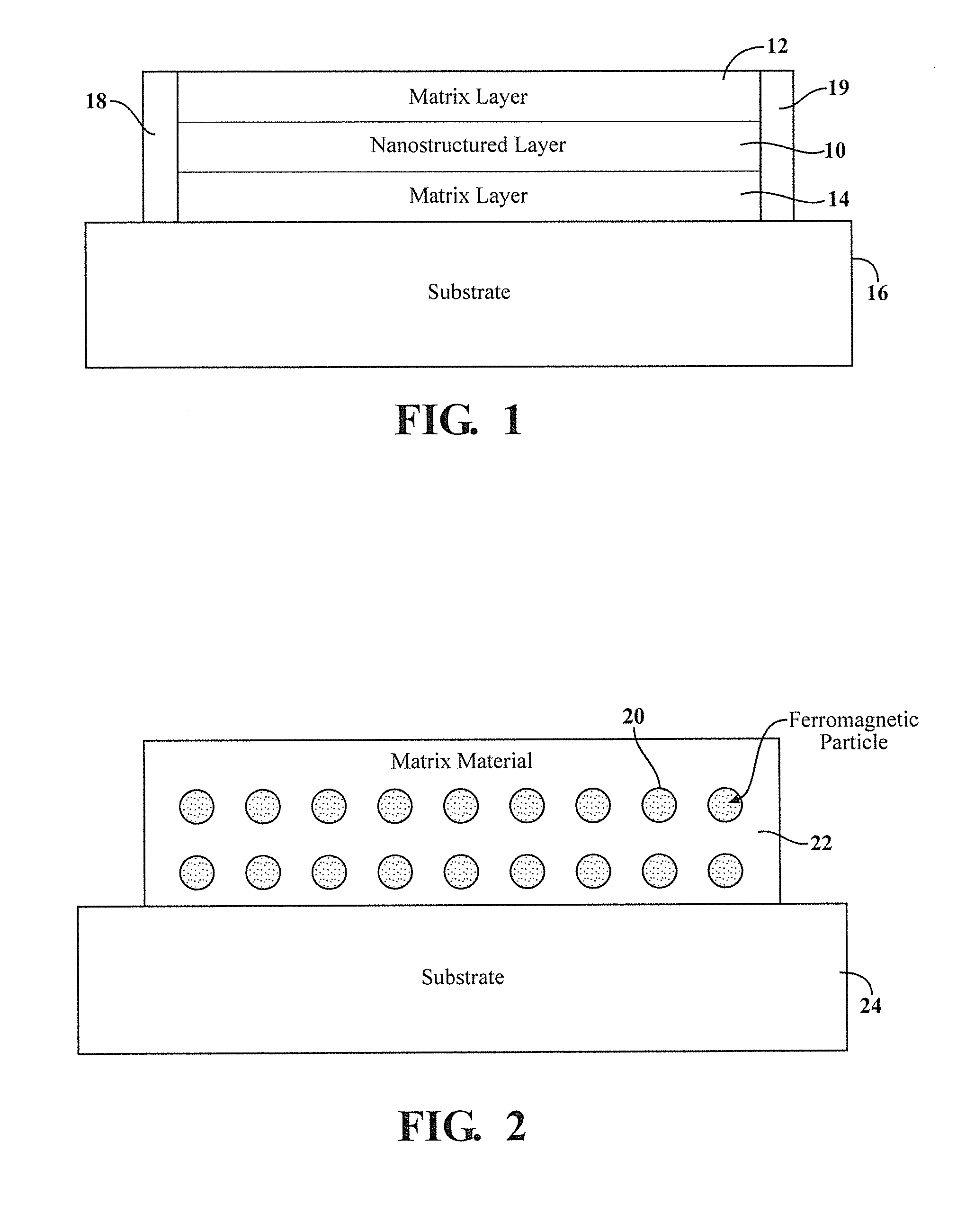
[0116]Example solid-state structures include nanoparticles and a matrix material. The nanoparticles may be magnetic nanoparticles, in particular ferromagnetic particles. Ferromagnetic nanoparticles may consist essenti...


PUM

PropertyMeasurementUnit
temperatureaaaaaaaaaa
thicknessesaaaaaaaaaa
thicknessaaaaaaaaaa

Abstract

Examples of the present invention include apparatus and methods for monitoring aging of an item. A solid-state structure is located within, adjacent to, or otherwise proximate the item, the solid-state structure including nanostructures. The electrical resistance and/or magnetization of the solid-state structure is determined to determine the degree of aging of the item. In representative examples, the solid-state structure includes nanostructures of a metal, such as a ferromagnetic metal, within a non-magnetic matrix, such as a semimetal, semiconductor, or insulator.

Description

CROSS-REFERENCE TO RELATED APPLICATIONS[0001]This application claims priority from U.S. Provisional Application 61 / 476,044 filed Apr. 15, 2011, the contents of which are incorporated herein by reference.FIELD OF THE INVENTION[0002]Examples of the invention relate to methods and apparatus for monitoring aging processes, for example using a solid-state apparatus.BACKGROUND OF THE INVENTION[0003]Aging processes are significant in many commercial activities, including handling of perishable items such as food and medicine, part lifetimes in engineering applications, process control, and the like. A typical approach is to determine an end-of-life date as a fixed time period from the initial manufacture. However, this fails to account for variations in temperature or other ambient conditions during the lifetime.[0004]Hence, there is a need for improved methods and apparatus allowing monitoring of aging processes in a variety of applications.SUMMARY OF THE INVENTION[0005]Examples of the pr...

Claims


Application Information

Patent Timeline
Patent Type & Authority Applications(United States)
IPC IPC(8): G01N27/04G01R27/08B82Y99/00
CPCB82Y40/00B82Y30/00G01N27/041G01N33/04G01N33/14
Inventor KENNING, GREGORY G.
Owner INDIANA UNIVERSITY OF PENNSYLVANIA
Why Eureka
Try Eureka