Method and circuit arrangement for checking the rotor position of a synchrounous machine

Active Publication Date: 2013-05-30
CONTINENTAL TEVES AG & CO OHG
View PDF13 Cites 15 Cited by
  • Summary
  • Abstract
  • Description
  • Claims
  • Application Information

AI Technical Summary

Benefits of technology

[0003]Electronically-commutated synchronous machines with a permanently-excited rotor and a stator provided with phase windings, also known as brushless dc motors, enjoy great popularity. They are characterized by low wear, and by their limited electromagnetic or acoustic interference, and show a high degree of efficiency. The influx of current to typically three stator windings generates a magnetic field, in which the permanently-excited rotor in arranged. By the appropriate switchover (comm

Problems solved by technology

Although this method permits the elimination of minor angle errors, it does not permit the reliable detection of a defective sensor.
If the rotor position detected by the sensors is not consistent with the actual rotor position, malfunctions of various types may ensue.
In many cases, this may result in damage to the motor, the driven device or the motor control system.
During the determination of the rotor position, the curre

Method used


Image

  • Method and circuit arrangement for checking the rotor position of a synchrounous machine
  • Method and circuit arrangement for checking the rotor position of a synchrounous machine
  • Method and circuit arrangement for checking the rotor position of a synchrounous machine

Examples


Embodiment Construction

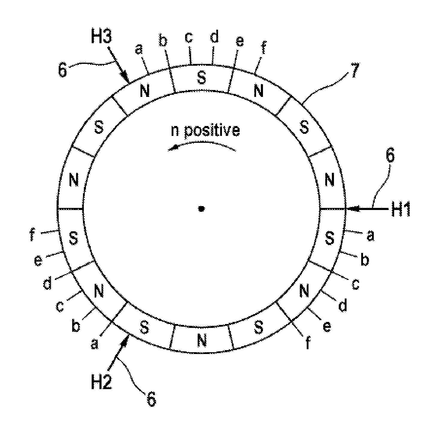
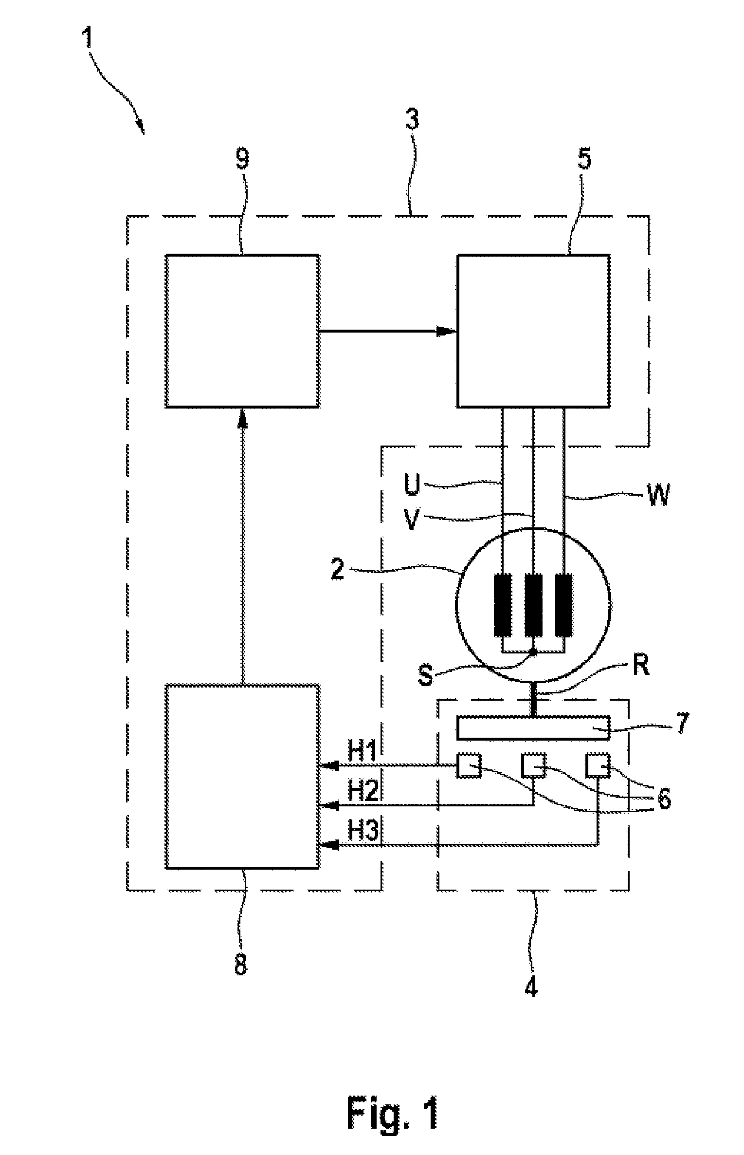
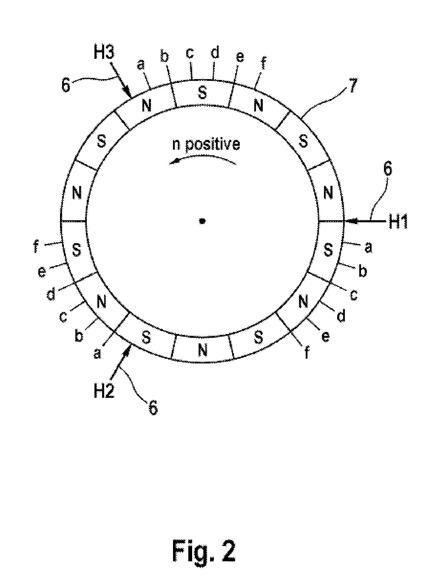
[0036]As represented in FIG. 1, an electronically-commutated synchronous machine 1 comprises an electromechanical energy converter 2, an electronic control device 3 and a rotor position sensor system 4. In addition to the use thereof as a drive mechanism, operation as a generator is also possible, whereby mechanical motion is converted into electrical energy accordingly. The stator is typically comprised of three phase windings, designated as U, V and W, which meet at a star point S. In principle, the delta connection of the phase windings would also be possible. The permanently-excited rotor is connected to a magnetic rotary encoder 7 via a bearing-mounted rotor shaft R. The magnetic field of the rotary encoder is scanned by digital Hall sensors 6. These sensors 6 will be enabled e.g. when they are located in the field of a magnetic north pole, and will conduct no current when a magnetic south pole is in the immediate vicinity. Hall switches of this type have a hysteresis, as a res...


PUM


Abstract

A method for validating a vehicle-to-X message, in which the message is received by an antenna arrangement having a least two antenna elements connected with a communication device. An electromagnetic field strength of the message is recorded based on different reception characteristics with different power densities, wherein the message includes an absolute position of a transmitter, and an absolute position of a receiver determined on the basis of global satellite navigation or on a map comparison. A first relative position of the transmitter is calculated from the absolute positions of the receiver and the transmitter. A second relative position is calculated from the ratio of the power densities or read out from a reference diagram. If a comparison of the first and second relative positions reveals a large degree of correspondence, the message is validated, and if a large degree of deviation is detected, the message is rejected.

Description

CROSS-REFERENCE TO RELATED APPLICATIONS[0001]This application claims priority to European Patent Application No. 10464007.3, filed Aug. 5, 2010 and PCT / EP2011 / 063055, filed Jul. 28, 2011.FIELD OF THE INVENTION[0002]The invention relates to a method and to a circuit arrangement for checking the rotor position of a synchronous machine.BACKGROUND AND SUMMARY OF THE INVENTION[0003]Electronically-commutated synchronous machines with a permanently-excited rotor and a stator provided with phase windings, also known as brushless dc motors, enjoy great popularity. They are characterized by low wear, and by their limited electromagnetic or acoustic interference, and show a high degree of efficiency. The influx of current to typically three stator windings generates a magnetic field, in which the permanently-excited rotor in arranged. By the appropriate switchover (commutation) of the currents flowing in the stator windings (or of voltages applied), a rotary motion is generated. Electronically...

Claims


Application Information

Patent Timeline
IPC IPC(8): G01B7/14
CPCH02P6/185G01B7/14H02P6/22
Inventor KAUFMANN, TOMSTAUDER, PETERBITSCH, CHRISTIANBUDIANU, BOGDANLEIDECK, JOCHEN
Owner CONTINENTAL TEVES AG & CO OHG
Why Eureka
Try Eureka