Check patentability & draft patents in minutes with Patsnap Eureka AI!

Light guide plate with tapering unit optical elements

a technology of optical elements and light guides, applied in the direction of lighting and heating apparatus, instruments, mechanical equipment, etc., can solve the problems of uneven amount of light exiting a light exit surface along the light guide direction, and achieve the effect of increasing the brightness of an imag

Active Publication Date: 2015-11-10
DAI NIPPON PRINTING CO LTD
View PDF25 Cites 3 Cited by
  • Summary
  • Abstract
  • Description
  • Claims
  • Application Information

AI Technical Summary

Benefits of technology

The present invention is a light guide plate that prevents too much light from leaking out near the edge of a screen. This allows for a brighter and clearer image to be displayed in the center of the screen. Overall, this improves the brightness and quality of the image that viewers see.

Problems solved by technology

However, in current edge-light type surface light source devices, the amount of light exiting a light exit surface is not completely uniform along the light guide direction: the amount of the exiting light tends to be large locally in an area of the light exit surface, lying close to a light source.
Thus, the fact that the amount of exiting light is large locally in an area of a light exit surface, lying close to a light source, is undesirable not only from the viewpoint of ensuring the uniformity of the amount of exiting light along the light guide direction but also from the viewpoint of efficiently using a limited amount of light emitted by a light source.

Method used


Image

  • Light guide plate with tapering unit optical elements
  • Light guide plate with tapering unit optical elements
  • Light guide plate with tapering unit optical elements

Examples


examples

[0215]The following examples illustrate the present invention in greater detail and are not intended to limit the invention in any manner.

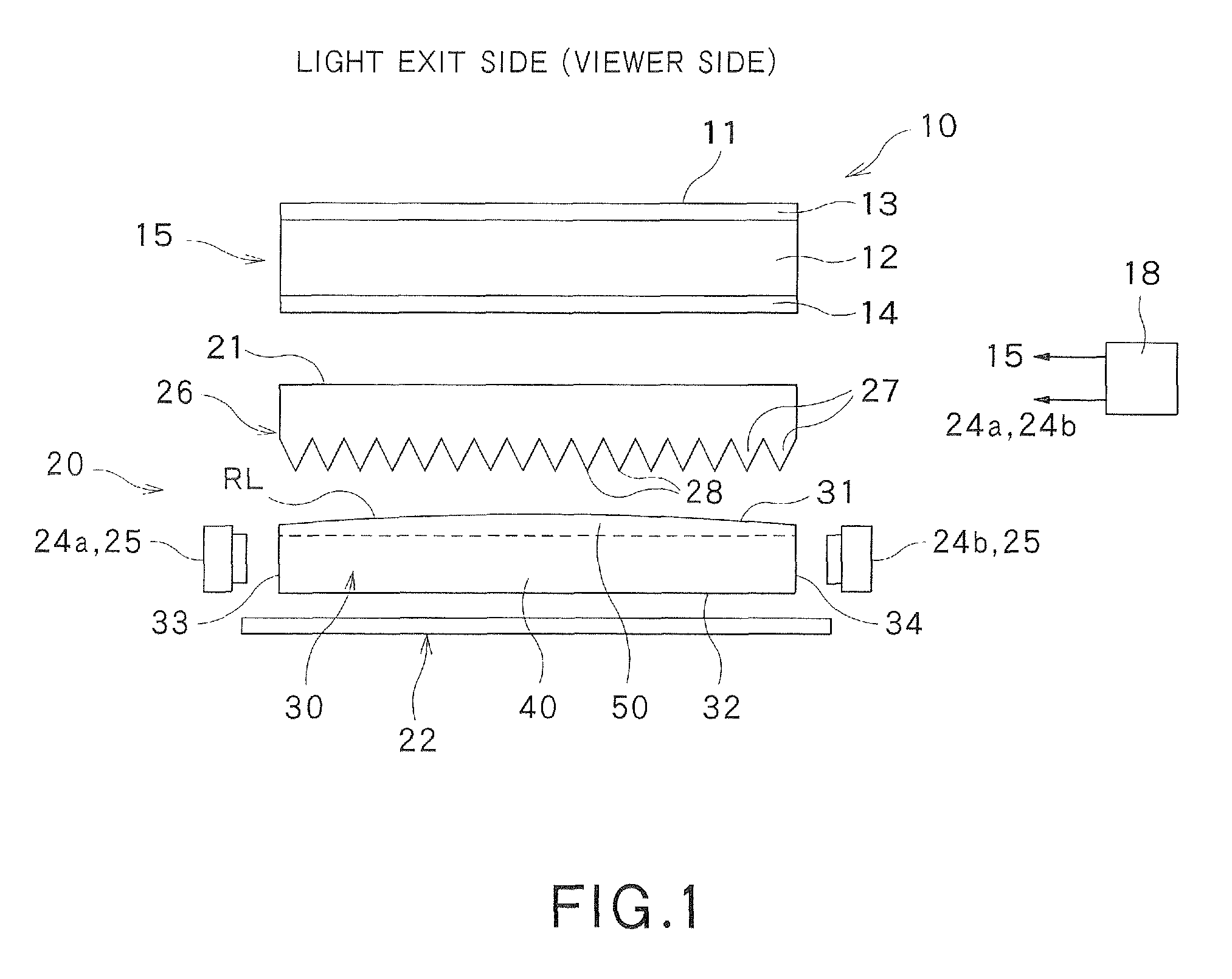
[0216]Surface light source devices (samples A to C) were prepared. Each surface light source consisted of a light guide plate, a light source, a reflective sheet and an optical sheet which were arranged in the same positional relationship as in the above-described embodiment. The surface light source devices of samples A to C were the same in the light source, the reflective sheet and the optical sheet, but differed from one another in the construction of the unit optical elements of the light guide plate as described below.

(Light Guide Plate)

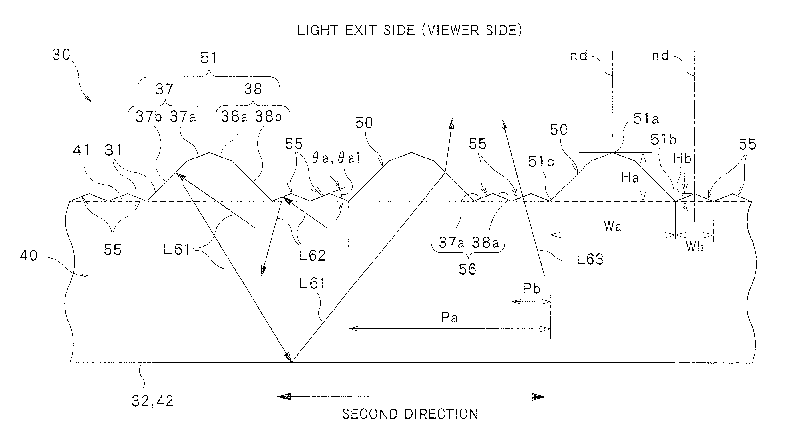
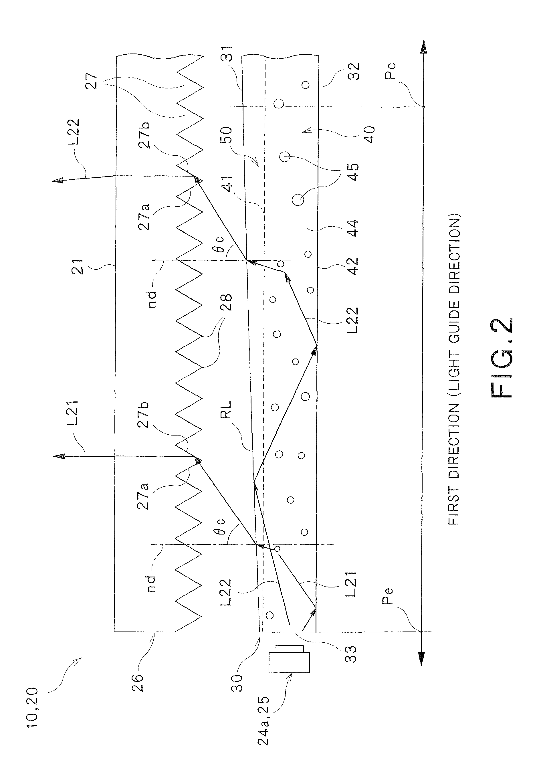
[0217]The light guide plate used consisted of a body portion and unit optical elements arranged on a one-side surface of the body portion. As in the above-described embodiment, a pair of opposing side surfaces of the light guide plate served as light entrance surfaces. Thus, the below-described light sources ...


PUM


Abstract

A light guide plate includes a body portion, first unit optical elements extending on the body portion in the light guide direction, and second unit optical elements disposed in between the first unit optical elements on the body portion. The width of each first unit optical element gradually decreases from that at the center to that at each end in the light guide direction. The ratio of the height to the width in each first unit optical element at the center is higher than the ratio of the height to the width in each second unit optical element.

Description

BACKGROUND OF THE INVENTION[0001]1. Field of the Invention[0002]The present invention relates to a light guide plate for guiding light, a surface light source device having the light guide plate, and a display device having the surface light source device.[0003]2. Description of Related Art[0004]Surface light source devices, which emit light from a planar surface, are widely used e.g. as a backlight which is incorporated in a liquid crystal display device and illuminates a liquid crystal display panel from the back (see e.g. JP 2007-227405A). Surface light source devices are roughly classified into direct-light type devices which have a light source disposed right behind an optical member, and edge-light type (also called side-light type) devices which have a light source disposed lateral to an optical member.[0005]Edge-light type surface light source devices have a structural feature that enables design of thin surface light sources as compared to direct-light type surface light so...

Claims


Application Information

Patent Timeline
Patent Type & Authority Patents(United States)
IPC IPC(8): F21V8/00
CPCG02B6/0038G02B6/0065G02B6/0041G02B6/0053
Inventor GOTO, MASAHIROSEKIGUCHI, HIROSHIYAMAMOTO, HIROSHI
Owner DAI NIPPON PRINTING CO LTD
Features
  • R&D
  • Intellectual Property
  • Life Sciences
  • Materials
  • Tech Scout
  • Unparalleled Data Quality
  • Higher Quality Content
  • 60% Fewer Hallucinations
Learn More