
Check valve

a check valve and valve body technology, applied in the direction of check valves, valve arrangements, thin material handling, etc., can solve the problem that reverse water flow can produce water pressure, and achieve the effect of excellent backflow prevention

Active Publication Date: 2015-12-08
YANG TSAI CHEN
View PDF1 Cites 1 Cited by
  • Summary
  • Abstract
  • Description
  • Claims
  • Application Information

AI Technical Summary

Benefits of technology

The objective of this invention is to provide a check valve that prevents water from flowing back into a hose and is not affected by reverse flow. The check valve is designed to ensure that the blocking portion remains securely in place, even at high water pressures. This prevents damage to the valve and ensures that the water source flows properly.

Problems solved by technology

However, when the check valve apparatus blocks water from flowing reversely, the reverse water flow can produce a water pressure.

Method used


Image

  • Check valve
  • Check valve
  • Check valve

Examples


Embodiment Construction

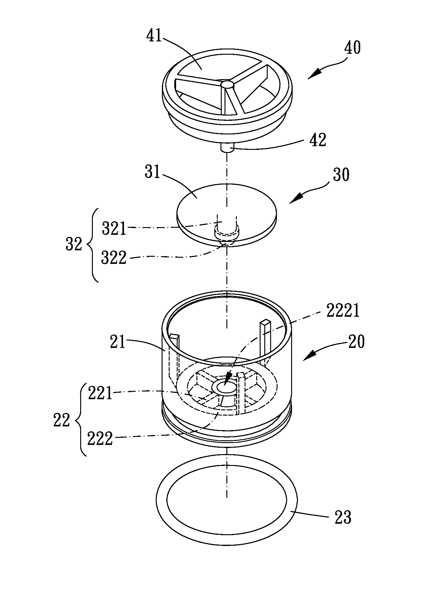
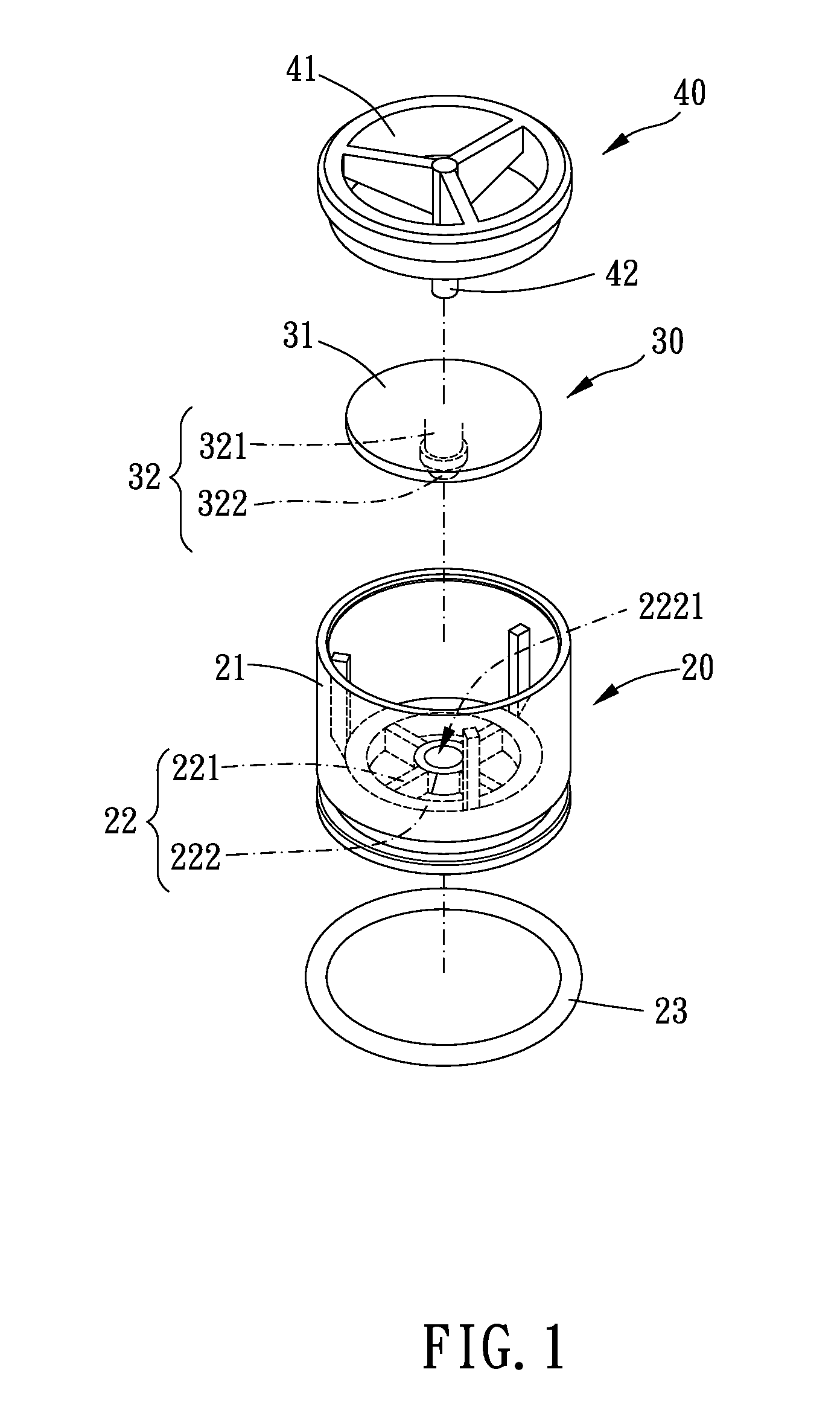
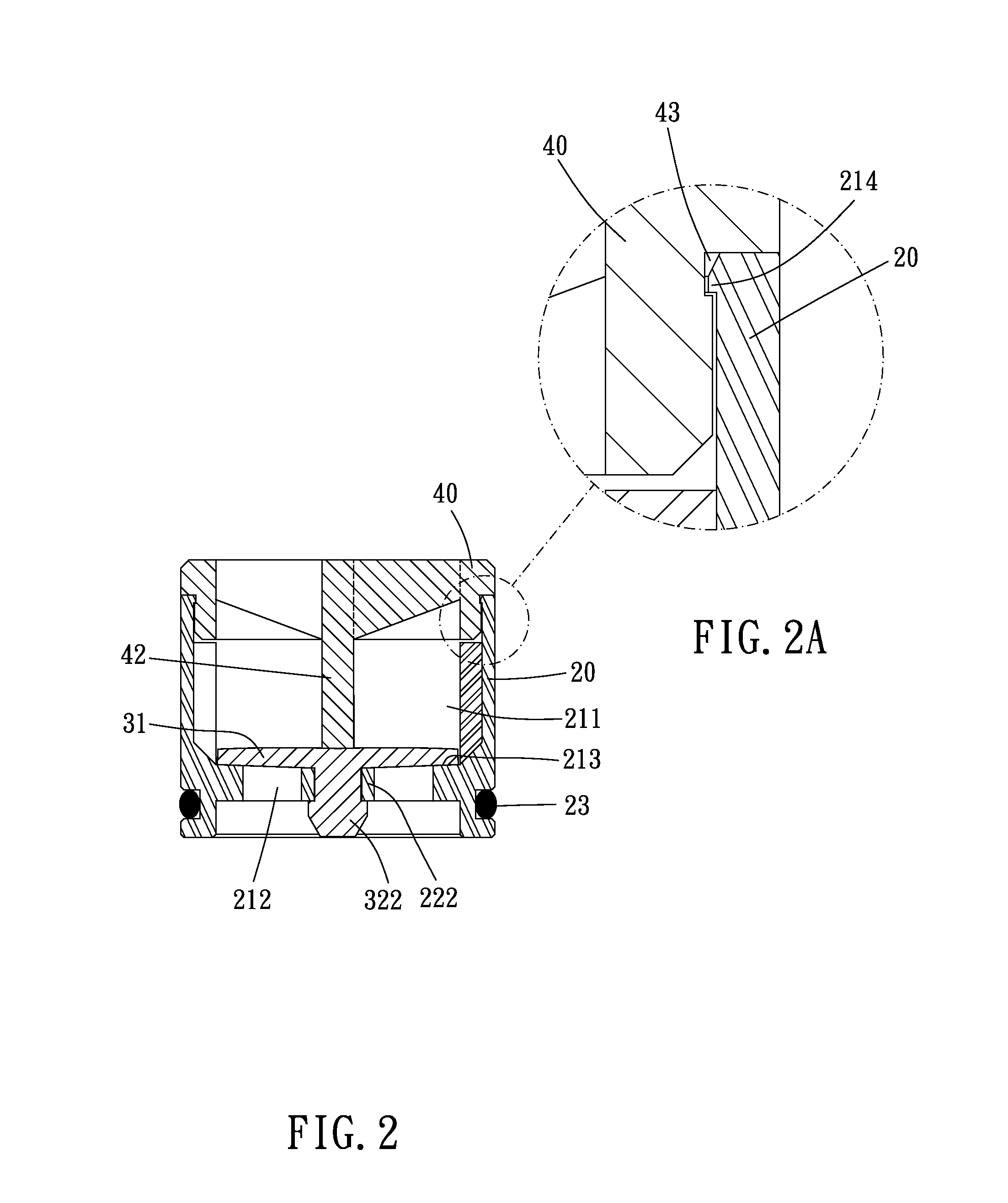
[0016]Please refer to FIGS. 1, 2 and 2A for a check valve of the present invention, including a position limiting member 20, a back-flow preventing member 30 and a lid body 40.

[0017]The position limiting member 20 includes a hollow tubular body 21 and a clasping portion 22. The tubular body 21 is provided for being disposed in a water hose, and an external diameter of the tubular body 21 can be designed in accordance with the hoses a user wants to assemble. In this embodiment, an O ring 23 is disposed around an external surface of the tubular body 21 (the external surface of the tubular body 21 is formed with an annular groove for disposal of O ring 23), and the O ring 23 can increase the sealing effect of the tubular body 21 and the water hose. The tubular body 21 is formed with a first axle hole 211 and a second axle hole 212 wherein the first axle hole 211 has a larger diameter than a diameter of the second axle hole 212. A stepped portion 213 is formed between the first and the ...


PUM


Abstract

A check valve is provided. The check valve includes a position limiting member, a back-flow preventing member and a lid body. The back-flow preventing member is disposed between the position limiting member and the lid body, and a blocking portion of the back-flow preventing member is flexible. When the blocking portion is impacted by an external water source, a gap will be formed between an external peripheral verge of the blocking portion and a stepped portion of the position limiting member to allow the water source to flow through the position limiting member. When the blocking portion is impacted by a reverse water source, the external peripheral verge of the blocking portion is abutted against the stepped portion to unallow the water source to flow through the position limiting member.

Description

BACKGROUND OF THE INVENTION[0001]1. Field of the Invention[0002]The present invention relates to a check valve apparatus which can prevent fluids from flowing reversely.[0003]2. Description of the Prior Art[0004]The main object of check valve apparatuses is to allow fluids to flow toward the same direction and to block fluids from flowing reversely through the design of the valve. Please refer to TW 509300 for a conventional check valve apparatus. TW 509300 disclosed an integrally formed rubber body, wherein an end is a round water inlet, the other end is a water outlet with two side bodies gradually slanted forward, two side bodies of the furthest forward end of the water outlet are air tight, a front end of a ring body of the round inlet is formed with two semi-circle water-stopping rings, a step face in the upper part is formed with a ring trough, and two sides are formed with reinforcing bodies so as to prevent water from flowing reversely.[0005]However, when the check valve app...

Claims


Application Information

Patent Timeline
Patent Type & Authority Patents(United States)
IPC IPC(8): F16K15/14
CPCF16K15/148Y10T137/7879
Inventor YANG, TSAI-CHEN
Owner YANG TSAI CHEN
Learn More