Turbojet engine nacelle with translatable upstream cowl

a technology of turbojet engine and nacelle, which is applied in the direction of jet propulsion plant, turbine/propulsion air intake, power plant arrangement/mounting, etc., can solve the problems of affecting the not being able to monitor the equipment fully, and affecting the overall performance of the engine,

Active Publication Date: 2015-12-15
SAFRAN NACELLES
View PDF16 Cites 2 Cited by
  • Summary
  • Abstract
  • Description
  • Claims
  • Application Information

AI Technical Summary

Benefits of technology

[0015]Thus, by providing guide means positioned as close as possible to an interface with an attachment pylon, the reaction and transmission of the stresses to the pylon via the guide means are considerably improved. It follows that it is possible to use fewer guide means, which lightens the nacelle assembly. Furthermore, in the event a pneumatic hose explodes, or in the event of an overpressure inside the nacelle, this better reaction of forces makes it possible to greatly reduce structural distortions in such a case.
[0020]Advantageously, at least one rail is equipped, at an upstream portion of said rail, with a reinforcing connecting rod intended to be connected to the pylon. Indeed, the upstream portion of the guide means is cantilevered relative to its fastening means, a support connecting rod therefore allows optimal support of this upstream portion.
[0024]Thus, in the closed position, the fitting mounted on the stationary (or mobile) structure is spaced away from the fittings mounted on the mobile (or stationary) structure, which prevents the transmission of forces, whereas in the open position, under the effect of the wind, for example, and the distortion of the mobile structure, the fitting fastened on the stationary (or mobile) structure bears against one or the other of the fittings mounted on the mobile (or stationary) structure, which allows forces to be reacted and eases all of the structures.
[0027]Such additional means for reacting circumferential forces (shearing pin 18) added in an area close to the guide means make it possible to help said guide means bear any parasitic force during operation. Fittings supporting force reaction axes are mounted in the surroundings of the rails surrounding the pylon close to the opening of the outer cowling. Complementary receiving fittings are mounted opposite each other on the fixed structure of the nacelle or the pylon. It should be noted that the additional means can indifferently be mounted on the stationary structure or the mobile structure and vice versa.

Problems solved by technology

This ice formation can be dangerous for the mechanical operation of the stationary and rotating parts of the engine and can cause a decrease in performance.
Despite the efforts made to optimize the positioning of the hatches and allow the easiest possible access, it is sometimes necessary to reach the internal equipment of the air intake structure using specific tools, such as an endoscope, which is not fully satisfactory in terms of monitoring this equipment.
Moreover, in the event it is necessary to replace part of the internal equipment, it will be necessary to take out the entire air intake structure, which requires significant tools and causes immobilization of the propulsion assembly and therefore of the airplane in general.
These constraints significantly reduce the integrity of the general aerodynamic line of the air intake structure, which the presence of access hatches further aggravates.
However, the number of guide means used makes the nacelle heavier and there is therefore a need to improve such a mobile cowl system requiring fewer guide rails while preserving good integrity of the structure.
Furthermore, the guide structures described in these documents are generally less suited to nacelles arranged at the fuselage of an aircraft and for which the attachment pylon is substantially horizontal.

Method used


Image

  • Turbojet engine nacelle with translatable upstream cowl
  • Turbojet engine nacelle with translatable upstream cowl
  • Turbojet engine nacelle with translatable upstream cowl

Examples


Embodiment Construction

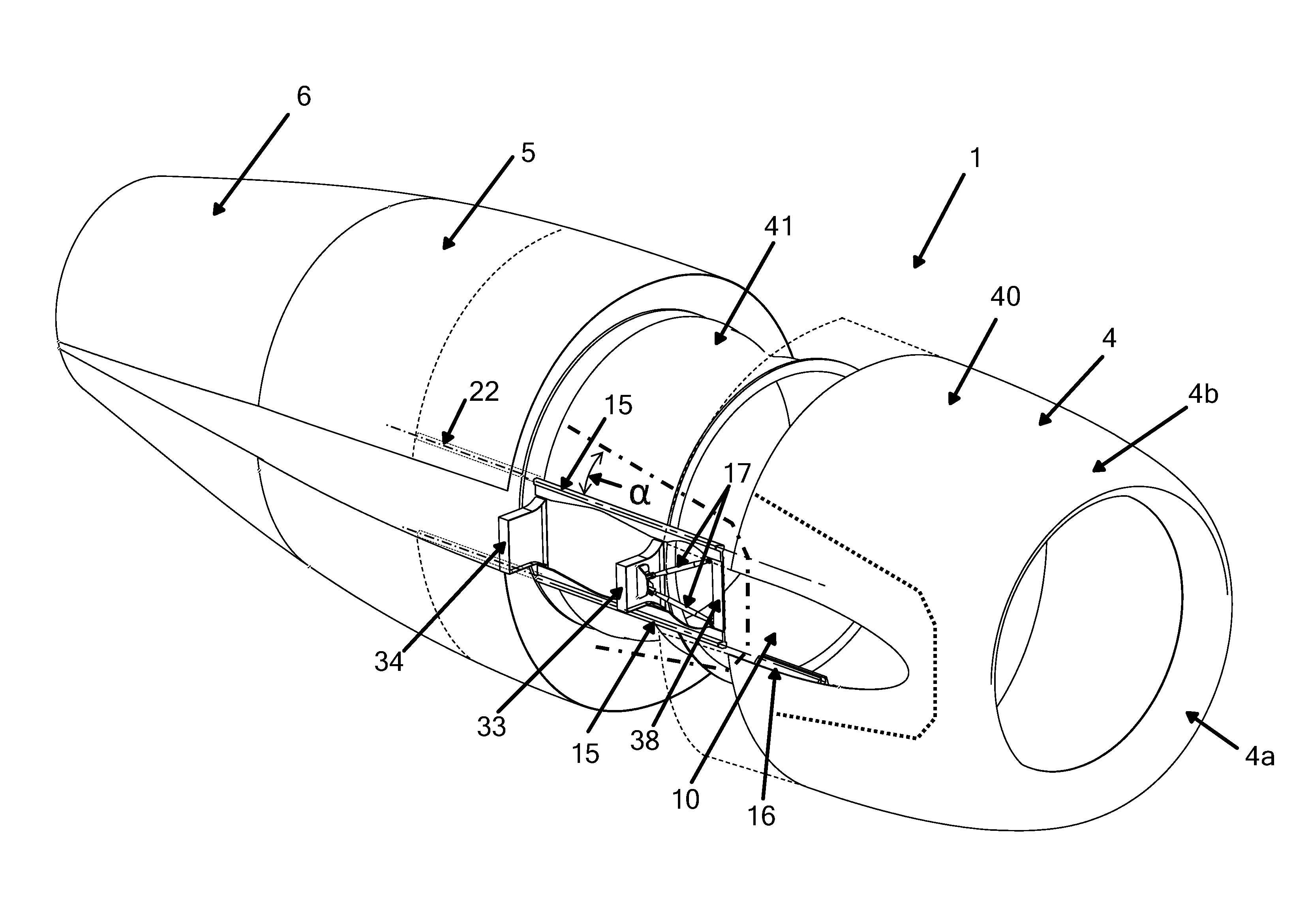
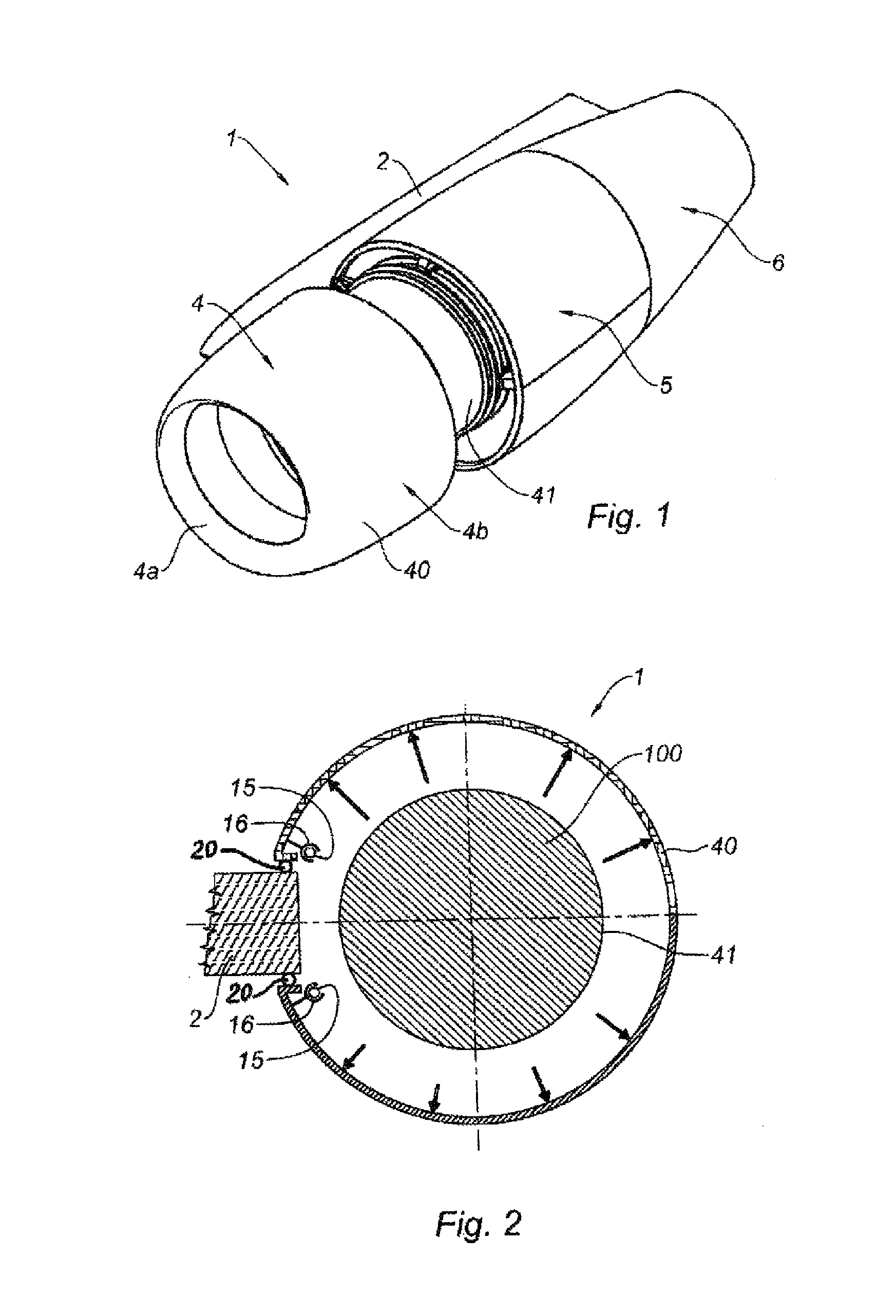
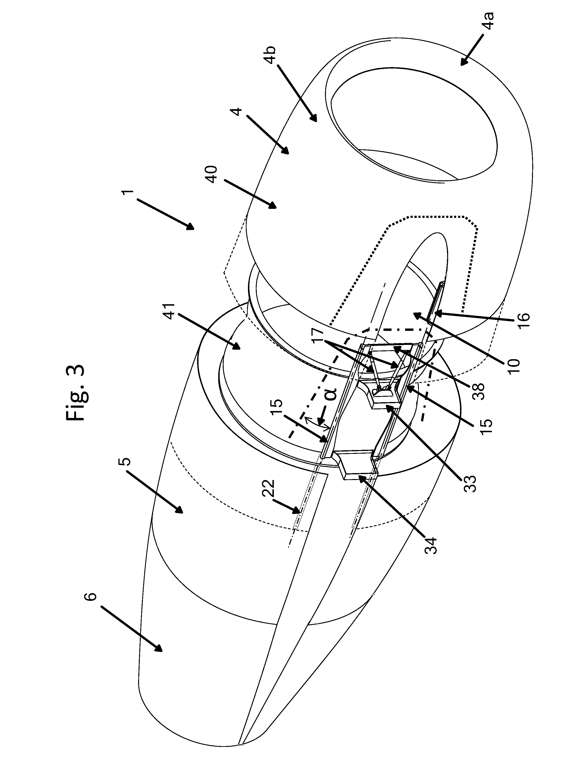
[0039]A nacelle 1 according to the invention, as shown in FIG. 1, constitutes a tubular housing for a turbojet engine 100 whereof it serves to channel the flows of air that it generates by defining inner and outer aerodynamic lines needed to obtain optimal performance.

[0040]More specifically, the nacelle shown in FIG. 1 is intended to equip an airplane of the business or tourism type. The propulsion assemblies of such airplanes are generally fastened at their fuselages via a substantially horizontal pylon 2.

[0041]In general, the nacelle 1 has a structure comprising a forward section forming an air intake 4, a central section 5 surrounding a fan and a compressor body (not shown) of the turbojet engine, and a rear section 6 able to house a thrust reverser system.

[0042]The air intake 4 is divided into two zones, i.e. on one hand, an air intake lip 4a adapted to allow optimal collection towards the turbojet engine 100 of the air necessary to supply the fan and the internal compressors o...


PUM


Abstract

Turbojet engine nacelle (1) comprising an air intake structure (4) able to channel a flow of air towards a fan of the turbojet engine, and a central structure (5) intended to surround said fan and to which the air intake structure is attached in such a way as to ensure aerodynamic continuity, the central structure comprising, on the one hand, a casing intended to surround the fan and, on the other hand, an outer structure, characterized in that the air intake structure comprises a longitudinal outer panel (40) incorporating an air intake lip (4a) and which may extend so far as to incorporate at least part of the outer structure of the central section and beyond, said longitudinal outer panel being translationally mobile between an operating position in which the outer panel ensures the aerodynamic continuity of the outside of the nacelle (1), and a maintenance position in which the outer panel (40) is set away from the outer structure of the central section and the air intake lip (4a) is set away from the inner panel of the air intake structure, characterized in that the longitudinal outer panel (40) is associated with guide means of the rails (15) / slide (16) type, at least part of said guide means being positioned as close as possible to an interface with a pylon (2) to which the nacelle is attached.

Description

TECHNICAL FIELD[0001]The present invention relates to a turbojet engine nacelle comprising an air intake structure able to channel a flow of air towards a fan of the turbojet engine and a central structure intended to surround said fan and to which the air intake structure is attached.BACKGROUND[0002]An airplane is propelled by one or more propulsion assemblies comprising a turbojet engine housed in a tubular nacelle. Each propulsion assembly is attached to the airplane by a pylon situated generally under a wing or at the fuselage.[0003]A nacelle generally has a structure comprising an air intake upstream of the engine, a central section intended to surround a fan of the turbojet engine, a downstream section housing thrust reverser means and intended to surround the combustion chamber of the turbojet engine, and generally ends with a jet nozzle whereof the outlet is situated downstream of the turbojet engine.[0004]The air intake comprises, on one hand, an air intake lip adapted to a...

Claims


Application Information

Patent Timeline
Patent Type & Authority Patents(United States)
IPC IPC(8): F02C7/20F02C7/04B64D29/08
CPCB64D29/08F02C7/04B64D2033/0286
Inventor JORET, JEAN-PHILIPPEVAUCHEL, GUY BERNARDGUILLOIS, DENISBEILLIARD, STEPHANE
Owner SAFRAN NACELLES
Why Eureka
Try Eureka