Transmitting apparatus, stereo image data transmitting method, receiving apparatus, and stereo image data receiving method

a technology of receiving apparatus and transmitting apparatus, which is applied in the direction of color signal processing circuits, instruments, television systems, etc., can solve the problem of not having an interconnection guarantee for connections with other manufactures' sets

Active Publication Date: 2010-07-22
SONY CORP
View PDF10 Cites 132 Cited by
  • Summary
  • Abstract
  • Description
  • Claims
  • Application Information

AI Technical Summary

Benefits of technology

[0044]According to this invention, when the transmitting apparatus transmits stereo image data to the receiving apparatus (external device), the transmitting apparatus receives, from this external device, information on transmission modes for stereo image data that can be supported by the external device, and decides the transmission mode for the stereo image data to be transmitted. Also, the transmitting apparatus transmits, to the external device, information on the transmission mode for the stereo image data to be transmitted, thereby making it possible to perform transmission of stereo image data between devices in a favorable manner.

Problems solved by technology

In particular, there is no interconnection guarantee for connections with other manufactures' sets.

Method used


Image

  • Transmitting apparatus, stereo image data transmitting method, receiving apparatus, and stereo image data receiving method
  • Transmitting apparatus, stereo image data transmitting method, receiving apparatus, and stereo image data receiving method
  • Transmitting apparatus, stereo image data transmitting method, receiving apparatus, and stereo image data receiving method

Examples


Embodiment Construction

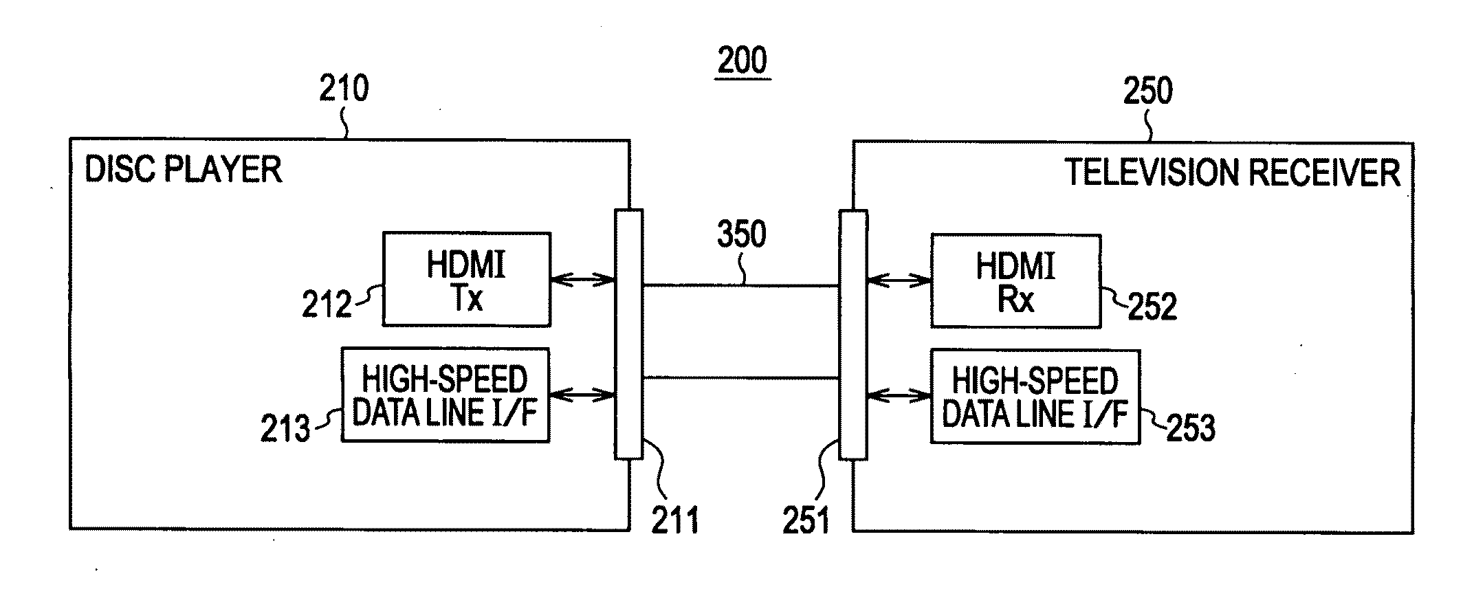
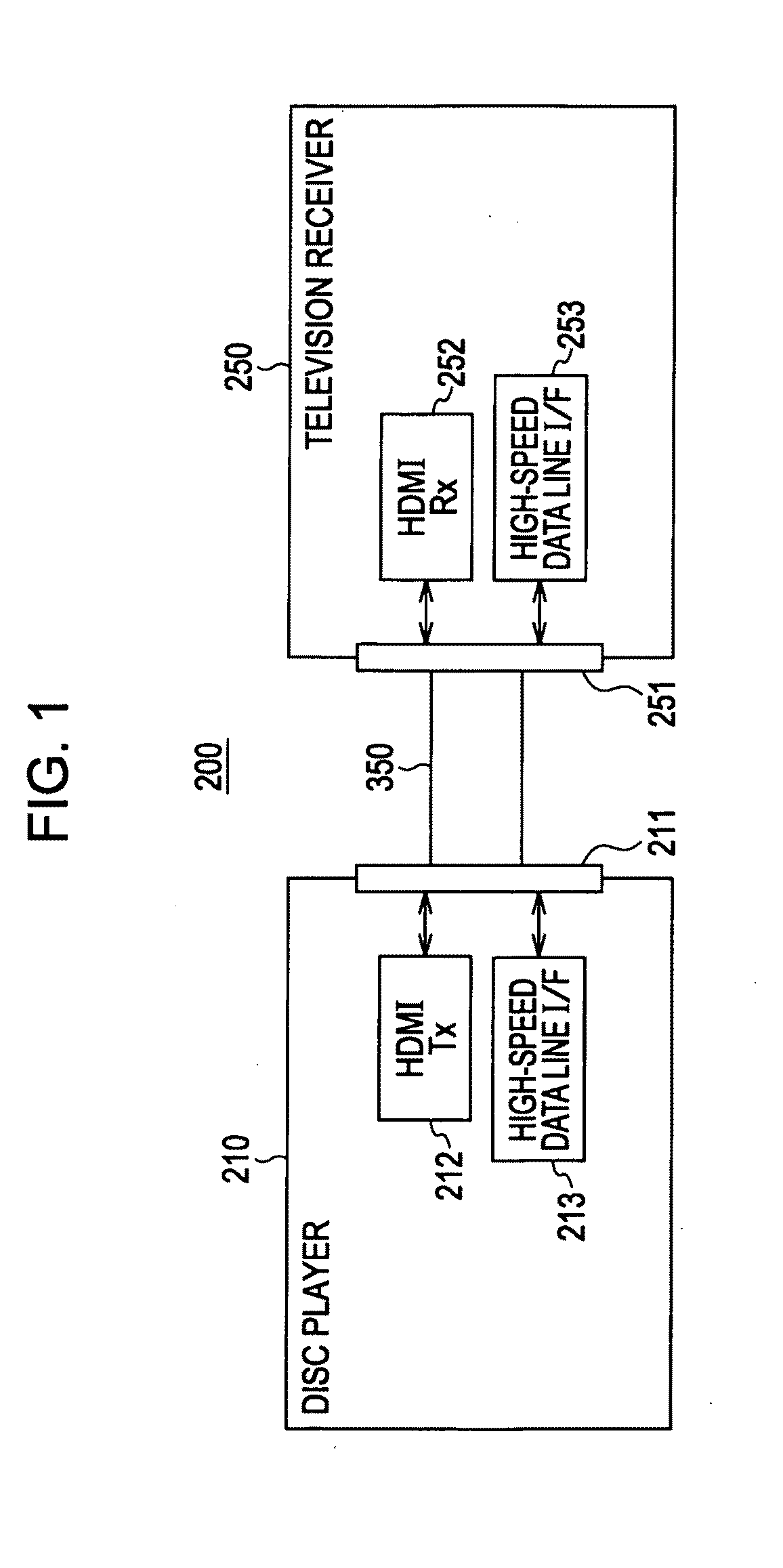
[0091]Hereinbelow, embodiments of this invention will be described with reference to the drawings. FIG. 1 shows an example of the configuration of an AV (Audio Visual) system 200 as an embodiment. The AV system 200 has a disc player 210 as a source device, and a television receiver 250 as a sink device.

[0092]The disc player 210 and the television receiver 250 are connected to each other via an HDMI cable 350. The disc player 210 is provided with an HDMI terminal 211 connected with an HDMI transmitting section (HDMI TX) 212 and a high-speed data line interface (I / F) 213. The television receiver 250 is provided with an HDMI terminal 251 connected with an HDMI receiving section (HDMI RX) 252 and a high-speed data line interface (I / F) 253. One end of the HDMI cable 350 is connected to the HDMI terminal 211 of the disc player 210, and the other end of the HDMI cable 350 is connected to the HDMI terminal 251 of the television receiver 250.

[0093]In the AV system 200 shown in FIG. 1, uncomp...


PUM


Abstract

The present invention makes it possible to perform transmission of stereo image data between devices in a favorable manner. A source device (disc player 210) receives E-EDID from a sink device (television receiver 250) via DDC of an HDMI cable 350. This E-EDID contains information on 3D image data transmission modes that can be supported by the sink device. On the basis of the information on 3D image data transmission modes from the sink device, the source device selects a predetermined transmission mode from among the 3D image data transmission modes that can be supported by the sink device. The sink device transmits 3D image data in the selected transmission mode to the sink device. For the convenience of processing in the sink device, the source device transmits information on the transmission mode for the 3D image data transmitted, to the sink device by using an AVI InfoFrame packet or the like. The sink device processes the 3D image data received from the source device in accordance with its transmission mode, thereby obtaining left eye and right eye image data.

Description

TECHNICAL FIELD[0001]This invention relates to a transmitting apparatus, a stereo image data transmitting method, a receiving apparatus, and a stereo image data receiving method. More specifically, this invention relates to a transmitting apparatus or the like with which, at the time of transmitting stereo image data to an external device, information on transmission modes for stereo image data that can be supported by the external device is received from this external device to decide the transmission mode for the stereo image data to be transmitted, and also transmission mode information on the stereo image data to be transmitted is transmitted to the external device, thereby making it possible to perform transmission of stereo image data between devices in a favorable manner.BACKGROUND ART[0002]In recent years, for example, HDMI (High Definition Multimedia Interface) is coming into widespread use as a communications interface for transmitting digital video signals, that is, uncom...

Claims


Application Information

Patent Timeline
Patent Type & Authority Applications(United States)
IPC IPC(8): H04N13/00H04N7/173H04N21/436H04N21/61
CPCG09G5/006H04N13/324G09G2340/02G09G2370/10G09G2370/12G09G2370/16H04N21/4122H04N21/4147H04N21/43632H04N21/4402H04N2213/003G09G3/003G09G5/005G09G2370/047G09G2370/22H04N21/43635H04N5/38H04N5/04H04N9/64H04N7/025H04N13/194H04N13/161H04N13/139H04N13/15H04N13/167H04N13/172G09G5/12H04N7/173H04N13/00
Inventor NAKAJIMA, YASUHISASUZUKI, KAZUYOSHITAO, AKIHIKOKAWAI, SHIGEHIRO
Owner SONY CORP
Why Eureka
Try Eureka