Physical device bonding

Inactive Publication Date: 2005-02-24
MICROSOFT TECH LICENSING LLC
View PDF26 Cites 130 Cited by
  • Summary
  • Abstract
  • Description
  • Claims
  • Application Information

AI Technical Summary

Benefits of technology

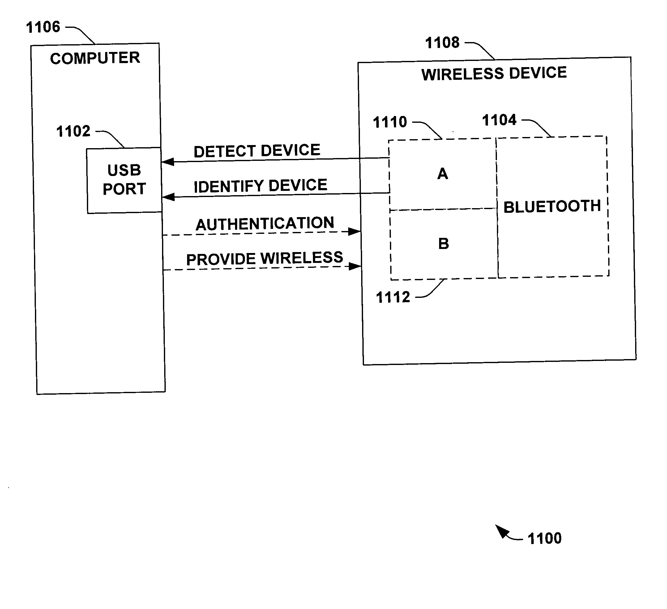
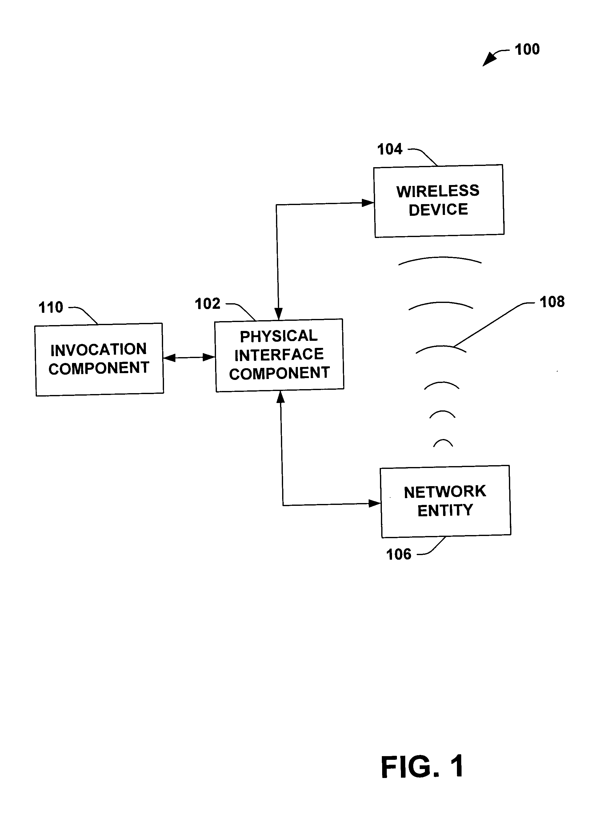
[0009] The subject invention provides for a physical device and host interface that facilitates device installation and authentication. As noted above, conventional host computer device installation and authentication schemes can be highly deficient as applied to wireless and/or remote devices. The subject invention provides a framework for installing and/or authenticating remote and wireless device(s) through a common physical interface.
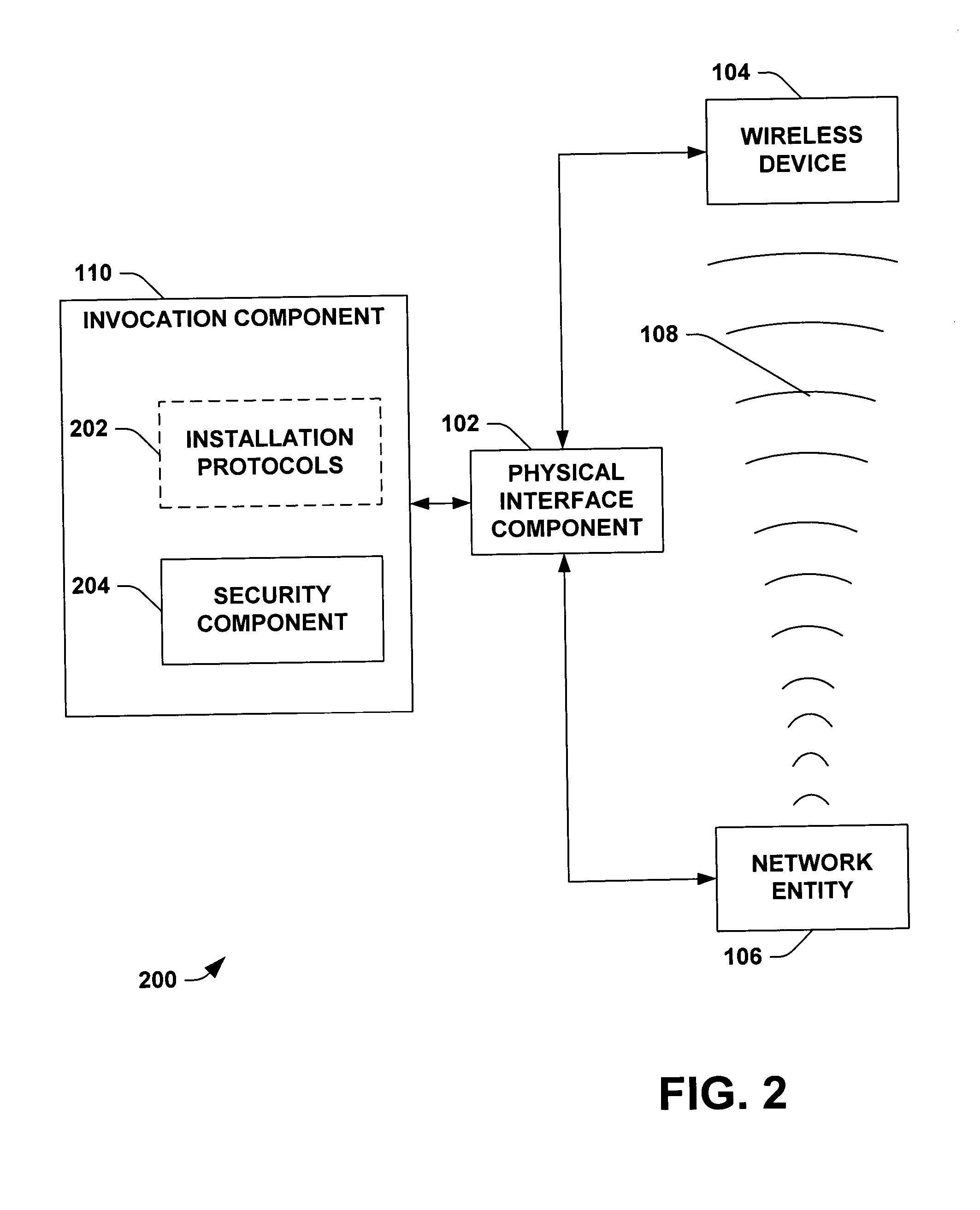
[0010] One particular aspect of the invention provides for an physical interface (e.g., cord, cable, cradle, dock, connector, coupler, touch pad, biological interface, biological materials, wand, universal serial bus (USB), . . . ) that, when engaged, prompts a host computing system to search for and install the interface. It is to be appreciated that the host computing system need not search for the wireless device to install and/or authenticate but rather the physical connection can initiate the information transfer of what and where the wireless device is to be installed and/or authenticated. Another aspect of the invention provides for a security component that facilitates transmission of authentication information without requiring user interaction. By connecting device(s) to the host via the electrical interface, a user indicates to the host a desire to install the device(s). While the device(s) and host are connected, they can exchange security information securely without the risk of others accessing “sniffing,” the data exchange over the air or network.
[0011] In addition, security information such as personal identification numbers (PINs) are not very secure when a user is required to enter PIN numbers etc. since they are limited by what a user is wi

Problems solved by technology

As noted above, conventional host computer device installation and authentication schemes can be highly deficient as applied to wireless and/or remote devices.
In addition, security information such as personal identification numbers (PINs) are not very secure when a user is required to enter PIN numbers etc. since

Method used


Image

  • Physical device bonding
  • Physical device bonding
  • Physical device bonding

Examples


Embodiment Construction

[0033] The present invention is now described with reference to the drawings, wherein like reference numerals are used to refer to like elements throughout. In the following description, for purposes of explanation, numerous specific details are set forth in order to provide a thorough understanding of the present invention. It may be evident, however, that the present invention may be practiced without these specific details. In other instances, well-known structures and devices are shown in block diagram form in order to facilitate describing the present invention.

[0034] As used in this application, the terms “component” and “system” are intended to refer to a computer-related entity, either hardware, a combination of hardware and software, software, or software in execution. For example, a component may be, but is not limited to being, a process running on a processor, a processor, an object, an executable, a thread of execution, a program, and a computer. By way of illustration...


PUM


Abstract

A system and/or method that facilitates the installation and/or authentication of a device by invoking installation protocols and/or authentication protocols for a non-physical connection. A physical interface component provides a physical connection between at least one wireless device and at least one network entity in which the installation protocols and/or authentication protocols can be exchanged. The physical interface component can utilize a token key to establish multiple non-physical connections with multiple wireless devices. Additionally, the physical interface component can utilize a daisy chain scheme to install and/or authenticate a wireless device.

Description

TECHNICAL FIELD [0001] This invention relates generally to a wireless device and a network entity (e.g., a host computer). More particularly, this invention relates to the installation and / or authentication of a non-physical connection between a wireless device and a network entity. BACKGROUND OF THE INVENTION [0002] Computer products and other networking equipment have emerged as one of the largest and fastest growing industries. With the rapid improvements made within the industry, electronic manufacturers continuously strive to satisfy the on-going demand for products providing functionality without restrictions such as, for example, size, power consumption, compatibility, ergonomics, software capability, lifetime, range, productivity, usable-interface, security, speed, portability, . . . . [0003] One restriction the electronic industries have vastly improved upon is providing a range or degree of freedom associated with employment of wireless networks and / or devices. Wireless ne...

Claims


Application Information

Patent Timeline
IPC IPC(8): G06F21/00H04L12/28H04L12/56H04L29/06H04L29/08
CPCG06F21/35G06F21/606G06F2221/2129G06F2221/2149H04L29/06H04L69/329H04L63/1441H04W12/06H04L67/34H04L67/04H04L63/0853H04W12/50H04L9/40
Inventor AULL, RANDALL E.THOMPSON, BERNARD J.
Owner MICROSOFT TECH LICENSING LLC
Why Eureka
Try Eureka