Improvements in and relating to displays

a technology for a display and a component is applied in the field of components for a display and a display apparatus, which can solve the problems of limiting the field of view (fov) and the colour bandwidth available from such waveguides, and unable to provide the total internal reflection required within the waveguide,

Active Publication Date: 2016-02-11
BAE SYSTEMS PLC
View PDF27 Cites 112 Cited by
  • Summary
  • Abstract
  • Description
  • Claims
  • Application Information

AI Technical Summary

Benefits of technology

[0006]At its most general, the invention implements an output (and preferably also an input) of guided light from a waveguide based on the principle of reflection rather than diffraction. Output of guided light is achieved by partial transmissions of the light through a surface of the waveguide which is prepared in such a way (e.g. bears an angularly reflective optical coating) as to inhibit

Problems solved by technology

Optical waveguides for display devices of this type typically release guided light from an output part by a process of diffraction for viewing, whereby guided light is diffracted within the waveguide to a direction which prohibits total internal reflection thereby rendering the waveguide no longer able to retain the guided light within it.
However, the diffraction gratings typically used to implement this input/output process are inherently dispersive thus lim

Method used


Image

  • Improvements in and relating to displays
  • Improvements in and relating to displays
  • Improvements in and relating to displays

Examples


first embodiment

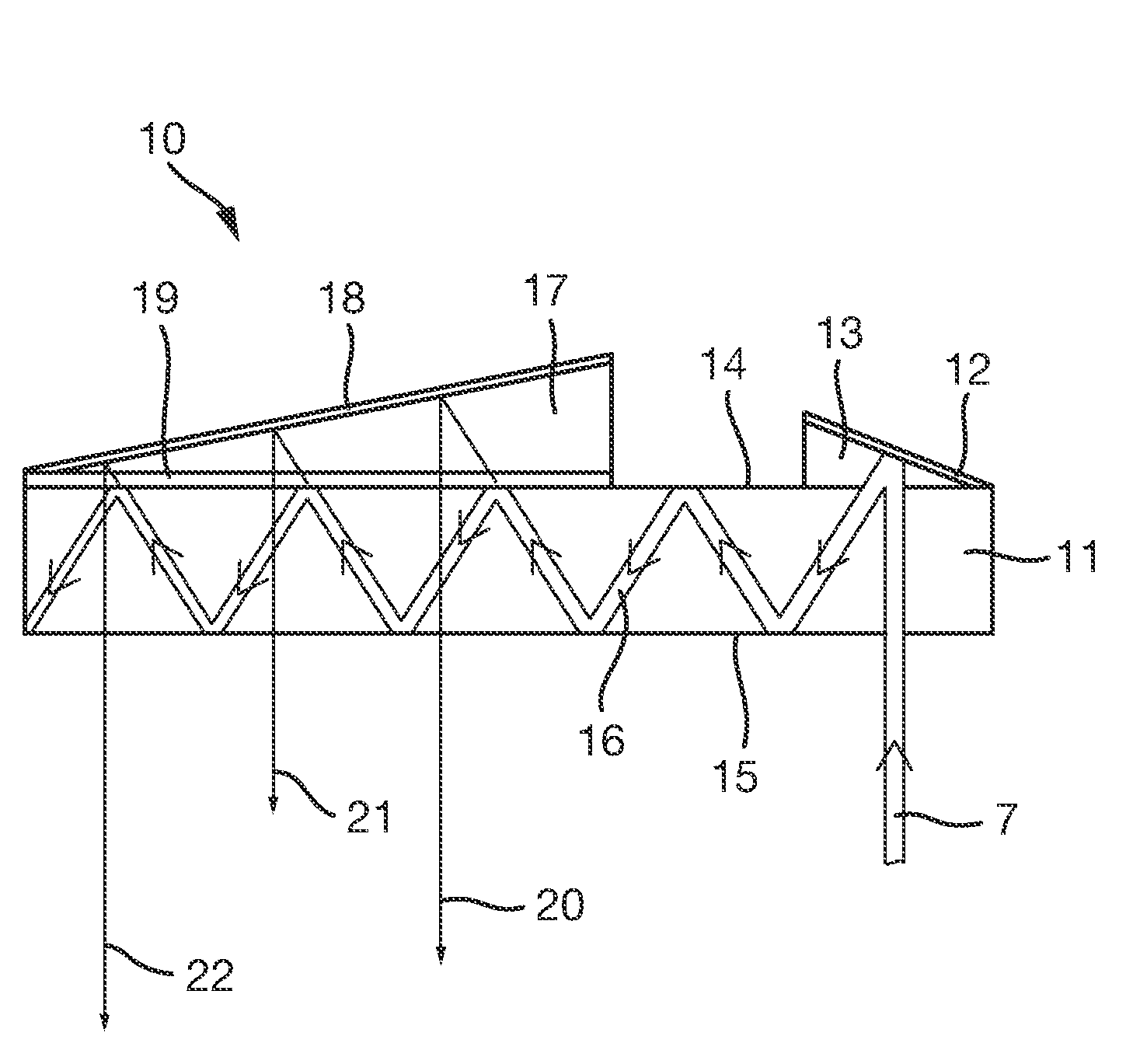
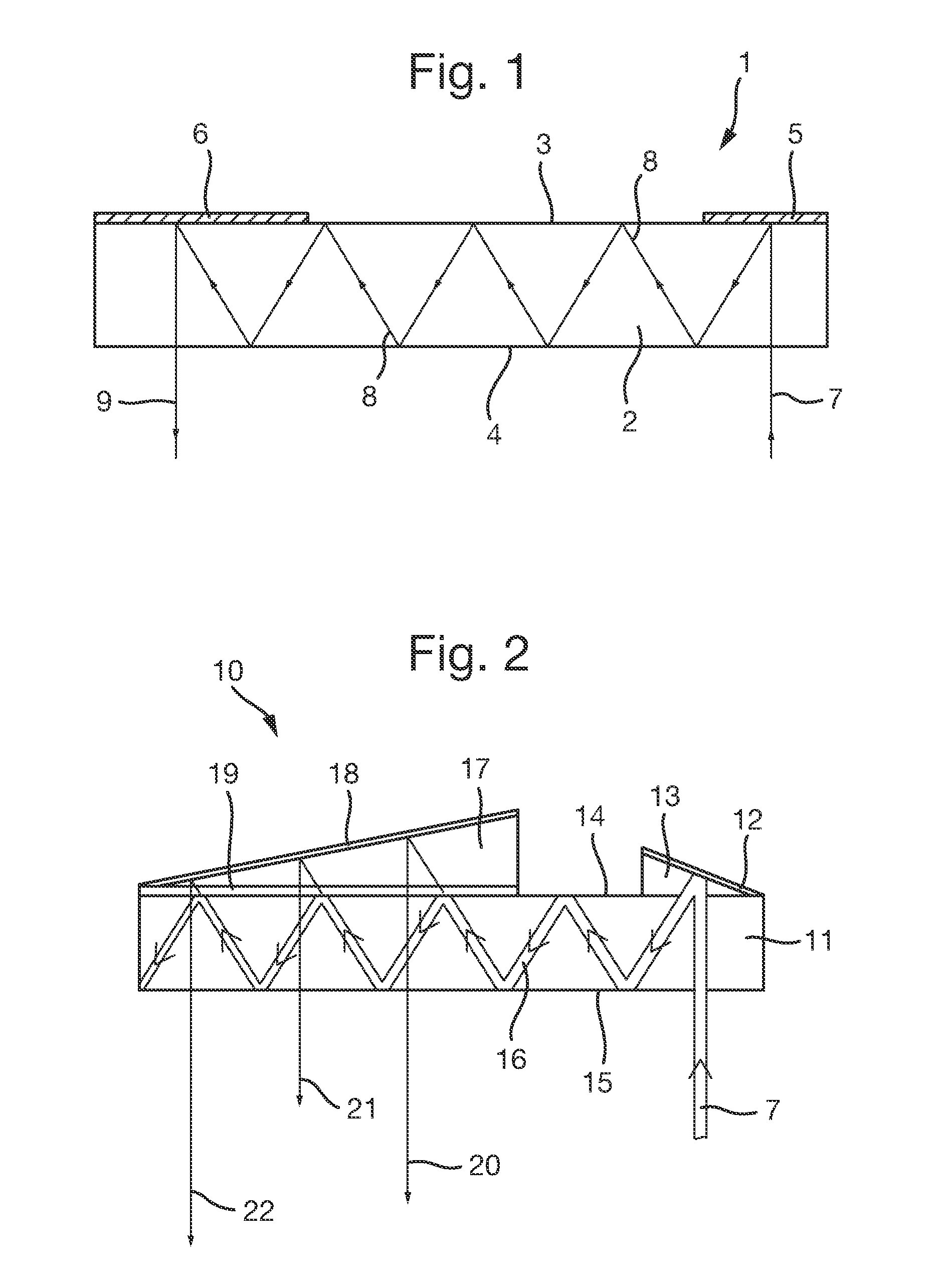
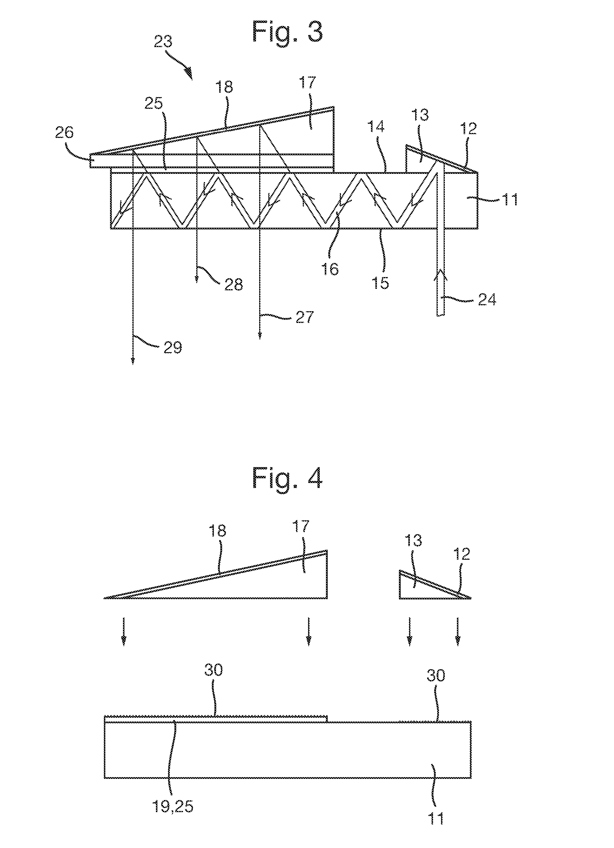
[0056]This 180-degree phase shift is such as to cause the orientation of the plane of oscillation (the polarisation plane) of the light transmitted light to change to an orientation which is perpendicular to the original polarisation orientation. Thus, if for example, incident light upon the quarter-wave plate is plane polarised in an orientation perpendicular to the plane of scattering of guided light within the waveguide (i.e. S-polarised light), then the finally output light—having undergone two transmissions through the quarter-wave plate—is plane polarised in an orientation parallel to the plane of scattering of guided light within the waveguide (i.e. P-polarised light). The angularly reflective optical coating 25 is arranged to provide the same function as is provided by the angularly reflective optical coating 19 arranged upon the slab waveguide illustrated in FIG. 1, and described above.

[0057]The angularly reflective optical coating 25 of the present embodiment may, indeed,...

embodiment 31

[0064]FIG. 5 schematically shows a further embodiment 31 of the invention which is a variant of the embodiment shown in FIG. 3. In this alternative embodiment, the output prism unit is replaced by an array of a plurality of small “micro-prisms”32 which each cover a respective part of the quarter-wave plate 26 upon which the array is mounted and the angularly reflective optical coating 26 upon which the quarter-wave plate is mounted. Collectively, the micro-prisms cover the whole of the quarter-wave plate and the angularly reflective optical coating. The hypotenuse of each micro-prism is coated with a reflective coating such as aluminium (Al) or a reflective dielectric material. The angle of inclination of the hypotenuse of each micro-prism is substantially common to each. Thus, the micro-prism array 32 serves the same function as the single output prism unit 17 of FIG. 3 yet presents a smaller structure in that the hypotenuse of any one micro prism rises less than the hypotenuse of ...


PUM

PropertyMeasurementUnit
Angleaaaaaaaaaa
Dimensionaaaaaaaaaa
Wavelengthaaaaaaaaaa

Abstract

An optical component for a display apparatus comprises an optical waveguide part (11) arranged to guide light therealong between surface parts thereof by internal reflection, an input part (13) arranged to receive light and direct the received light into the optical waveguide part, and an output part comprising a partially transmissive angularly reflective optical coating (25) arranged upon a surface part of the optical waveguide part. The output part is optically coupled to the input part by the optical waveguide part to receive guided light and to transmit some but not all of said guided light out from the optical waveguide part. The angularly reflective optical coating extends along a dimension of the optical waveguide part to expand the guided light in said dimension along the output part by repeated partial transmission thereof for output.

Description

FIELD OF THE INVENTION[0001]The invention relates to a component for a display, and to a display apparatus as well as a method for providing an optical display such as an optical display employing an optical waveguide. In particular, the invention is relevant to a display device in which image-bearing light is injected into a waveguide and is subsequently released from the waveguide for viewing, for example a helmet-mounted or head-up display device. In such devices, image-bearing light may be focussed at infinity.BACKGROUND[0002]Optical waveguides for display devices of this type typically release guided light from an output part by a process of diffraction for viewing, whereby guided light is diffracted within the waveguide to a direction which prohibits total internal reflection thereby rendering the waveguide no longer able to retain the guided light within it. Such light simply exits the waveguide without further propagation within the waveguide, and is thereby visible to a vie...

Claims


Application Information

Patent Timeline
IPC IPC(8): G02B27/01F21V8/00G02B27/00
CPCG02B27/0101G02B6/0031G02B6/0055G02B2027/0116G02B6/0053G02B27/0081G02B2027/0125G02B6/0056G02B6/0018G02B6/005G02B27/0172G02B5/045
Inventor VALERA, MOHMED SALIMSIMMONDS, MICHAEL DAVID
Owner BAE SYSTEMS PLC
Why Eureka
Try Eureka