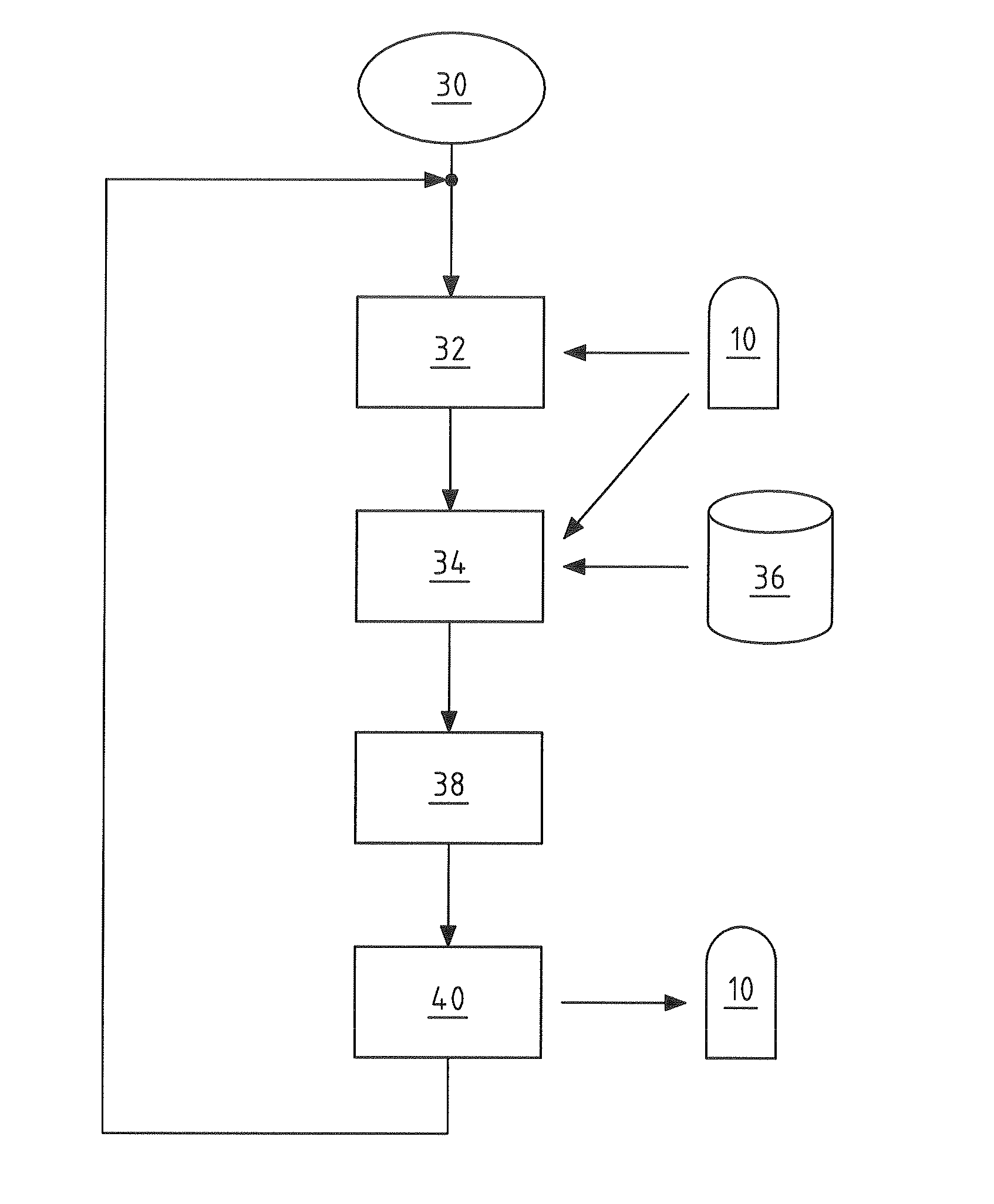
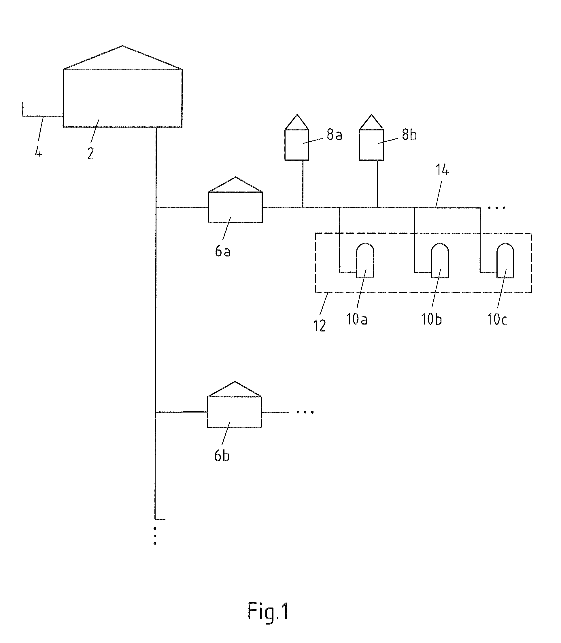
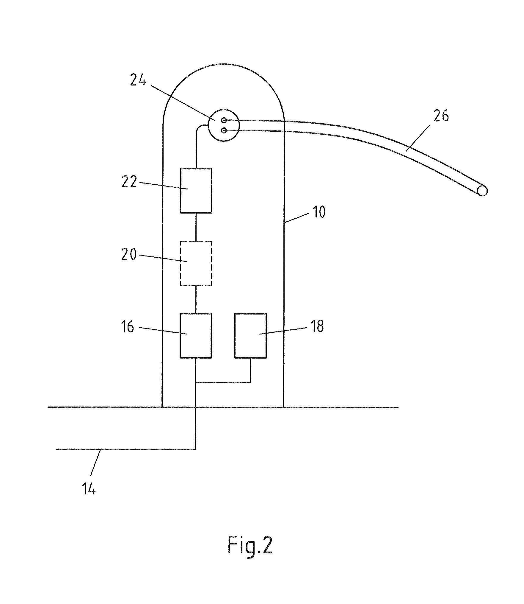
[0017]With the aid of the method according to the subject-matter, it is thus possible to reduce the need for a network
upgrade and at the same time make the required energy reliably available to the electrical vehicles.
[0023]Inside a vehicle, a charging
regulator may have knowledge of the
state of charge of a battery. The charging
regulator may furthermore have knowledge about the electrical power currently made available. With this information, and for example with further information about the battery temperature, a charging
regulator can create a charging prediction for an electrical vehicle. For example, a charging regulator may predict how long a charging process will still last until the battery has reached a predefined
state of charge. The charging regulator may also determine the appearance of a
current load curve for charging the electrical vehicle over the remaining charging duration. Thus, the charging regulator may for example establish that the required amperage at the end of the charging process will be reduced and there is therefore a falling
current load curve. For this reason, according to an advantageous embodiment, it is proposed that the compilation of the load prediction is additionally dependent on at least one charging prediction of an electrical vehicle, the charging prediction of an electrical vehicle comprising at least a charging duration and / or a
current load curve. This charging prediction may advantageously be transmitted from the charging regulator, or the electrical vehicle, to the
charging station. The
charging station can communicate this information in the group, so that with the aid of the charging prediction it is possible to create an improved load prediction.
[0026]According to an embodiment, it is also proposed that the reference charging parameters are communicated within the group and that a charging
station negotiates charging parameters with an electrical vehicle as a function of the reference charging parameters. If it is found in the load prediction that an increased load is probable in the near future, then the must charging parameter may take account of this and, for example, determine that a maximum charging
current strength of 16 A is allowed. If such a must charging parameter has been communicated within the group and an electrical vehicle connects to a charging
station, then it can be established in the charging parameters which the charging
station negotiates with the electrical vehicle that the electrical vehicle is only allowed to be charged with 16 A. The electrical vehicle, or the computer arranged in the electrical vehicle, may accept this charging parameter and begin to charge, or decline. If this charging parameter is declined, then the charging is not started at all. An overload in the group can therefore be avoided with the aid of the reference charging parameters.
[0029]According to an embodiment, it is proposed that at the start of a charging process, information about a required quantity of energy, a preferred charging duration, a preferred charging time and / or a charging regulator is sent from an electrical vehicle to a charging station. This function may possibly exist only in newer vehicles. In this case, the charging station may make an assumption about the charging duration and the charging time as well as the current load curve. At least a maximum charging amperage, a charging period, a charging duration and / or a maximum charging duration may also be determined and communicated to the electrical vehicle by the charging station as a function of the reference charging parameters and the information from the electrical vehicle. This may be done depending on the capabilities of the charging regulator. This negotiation of charging parameters makes it possible to negotiate the optimal charging parameters with the electrical vehicle, according to the capabilities and requirements of the electrical vehicle and the restrictions of the reference charging parameters. Here, on the one hand, the requirements of the electrical vehicle for a particular quantity of energy can be accommodated. On the other hand, for example, a customer may have been contractually guaranteed a minimum charging amperage of 20 A. If so, this must be taken into account when negotiating the charging parameters while taking the reference charging parameters into account.
[0030]According to an embodiment, it is proposed that the group is allocated to at least one low-
voltage transformer station of a low-
voltage level. For example, such a
transformer may provide a power of from 400 to 1000 kVA. This station power must be distributed intelligently between the charging stations connected to this transformer, which is done by creating a load prediction and determining reference charging parameters. An overload
scenario can therefore be avoided in the low-voltage level.


