Magnetic toner

a toner and magnetic technology, applied in the field of magnetic toners, can solve the problems of excessive charge of a portion non-uniform charging of the magnetic toner, and inability to uniformly charge the magnetic toner, so as to prevent fogging and reduce density

Active Publication Date: 2015-12-15
CANON KK
View PDF16 Cites 34 Cited by
  • Summary
  • Abstract
  • Description
  • Claims
  • Application Information

AI Technical Summary

Benefits of technology

[0034]The present invention can provide a magnetic toner that can prevent fogging and density reduction from occurring in the initial image after standing in a severe environment.

Problems solved by technology

For example, printers, which previously were used mainly in office environments, have also entered into use in severe environments, and the generation of stable images even under these circumstances has become critical.
When, for example, the coverage of the magnetic toner by an external additive is inadequate or the magnetic toner is used in a severe environment, e.g., a high-temperature, high-humidity environment (in the following, a severe environment refers to conditions of 40° C. and 95% RH), its triboelectric charging may not proceed uniformly and charging of the magnetic toner may then become nonuniform.
As a result, a phenomenon can occur in which only a portion of the magnetic toner is excessively charged, so-called charge-up, and various image defects may then occur.
In particular, when the developing sleeve has been downsized as referenced above, the development zone of the development nip region is narrowed and the flight of the magnetic toner from the developing sleeve is made more difficult.
As a consequence, a portion of the magnetic toner is prone to remain on the developing sleeve and a trend of greater charging instability sets in.
For example, a reduction in image density can occur when charged-up toner remains on the developing sleeve, while an image defect such as fogging in the nonimage areas can be caused when the toner charge is nonuniform.
Furthermore, when used after standing for a while in a severe environment, the aggregative behavior exhibited by the toner is increased due to the pressure on the toner in the developer container.
However, the flowability and aggregative behavior immediately after standing in a severe environment of higher temperature and higher humidity are in particular not adequately addressed, and there is still room for improvement with regard to the reduced initial density after standing in a severe environment.
There is room for improvement with these problems in particular when a small-diameter developing sleeve is installed since aggregation of the magnetic toner on the developing sleeve causes the developing performance to deteriorate.
However, the problem of charge up produced due to the detachment of large-diameter strontium titanate particles is not adequately addressed, and there is room for improvement with these problems in particular when a small-diameter developing sleeve is installed since the developing zone is then narrow and the charged-up toner undergoes development with difficulty.
The charging stability of magnetic toners is again not adequately addressed in these cases.
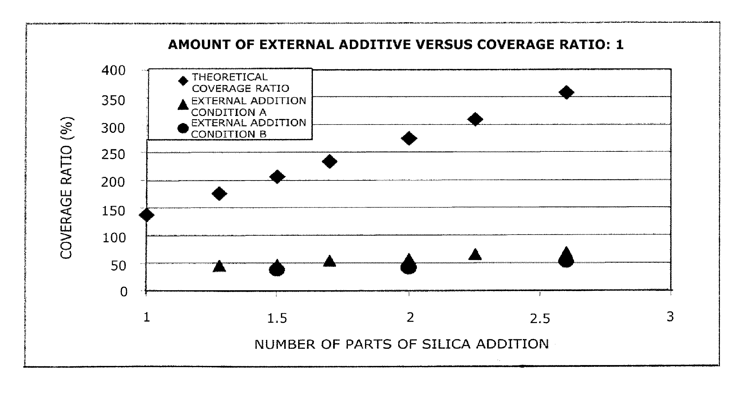
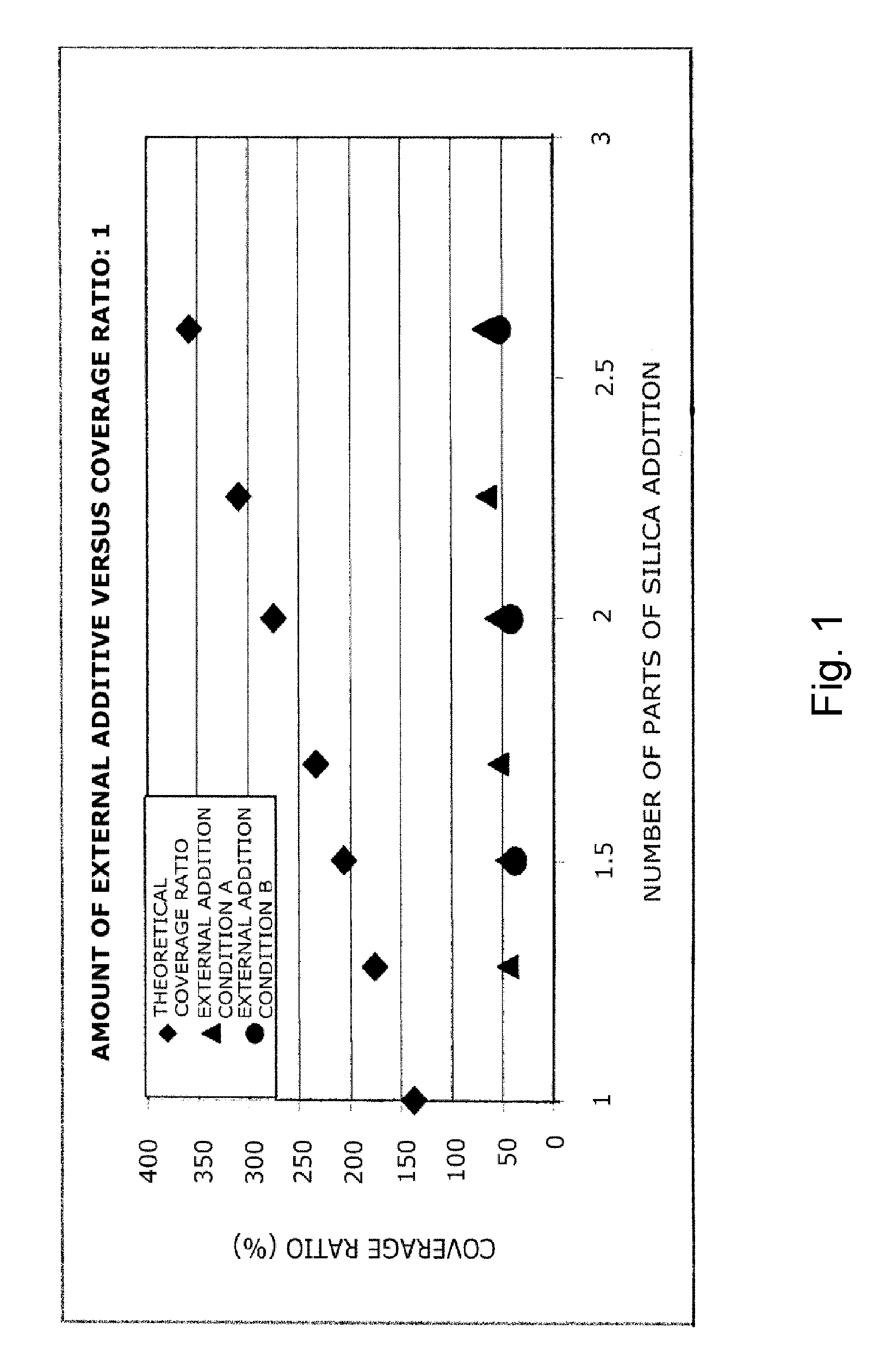
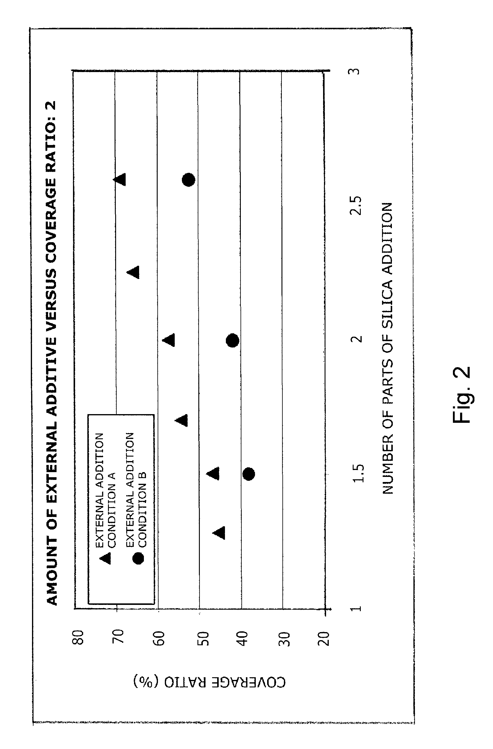
However, the actual state of binding by external additives may be substantially different from the value calculated assuming the toner to be a sphere, and, for magnetic toners in particular, achieving the effects of the present invention without controlling the actual state of external additive binding has proven to be entirely unsatisfactory.

Method used


Image

  • Magnetic toner
  • Magnetic toner
  • Magnetic toner

Examples


example 1

The Image-Forming Apparatus

[0344]The image-forming apparatus was an LBP-3100 (Canon, Inc.), which was equipped with a small-diameter developing sleeve that had a diameter of 10 mm; its printing speed had been modified from 16 sheets / minute to 20 sheets / minute. In an image-forming apparatus equipped with a small-diameter developing sleeve, the durability can be rigorously evaluated by changing the printing speed to 20 sheets / minute.

[0345]Using this modified apparatus and magnetic toner 1, an image check was performed under a normal-temperature, normal-humidity environment (under an NN environment, 23° C. / 50% RH), followed by standing for 30 days under a severe environment (40° C. / 95% RH) and then a 50-sheet image output test in one-sheet intermittent mode of a solid image.

[0346]According to the results, an excellent image, which had little fogging in nonimage areas and in which density reduction was suppressed, could be obtained even immediately after standing in a severe environment...


PUM

PropertyMeasurementUnit
number-average particle diameteraaaaaaaaaa
intensity of magnetizationaaaaaaaaaa

Abstract

The magnetic toner contains: magnetic toner particles containing a binder resin and a magnetic body; and inorganic fine particles present on the surface of the magnetic toner particles, wherein the inorganic fine particles present on the surface of the magnetic toner particles comprise strontium titanate fine particles and metal oxide fine particles, and the metal oxide fine particles containing silica fine particles, and optionally containing titania fine particles and alumina fine particles, and a content of the silica fine particles being at least 85 mass % with respect to a total mass of the silica fine particles, the titania fine particles and the alumina fine particles. In addition, the magnetic toner has a characteristic state of coverage, by the inorganic fine particles, of the magnetic toner particle surface, and the ratio [D4 / D1] of the weight-average particle diameter (D4) to the number-average particle diameter (D1) is in a prescribed range.

Description

TECHNICAL FIELD[0001]The present invention relates to a magnetic toner for use in, for example, electrophotographic methods, electrostatic recording methods, and magnetic recording methods.BACKGROUND ART[0002]Numerous methods are known for the practice of electrophotography. At a general level, these are methods in which a copied article is obtained by an image-forming procedure having a charging step in which an electrostatic latent image-bearing member is charged; an electrostatic latent image-forming step in which an electrostatic latent image is formed on the charged electrostatic latent image-bearing member; a step in which the electrostatic latent image is developed by magnetic toner carried on a magnetic toner-carrying member in order to form a magnetic toner image on the electrostatic latent image-bearing member; a transfer step in which this toner image on the electrostatic latent image-bearing member is transferred to a transfer material; a fixing step in which this toner ...

Claims


Application Information

Patent Timeline
Patent Type & Authority Patents(United States)
IPC IPC(8): G03G9/087G03G9/083G03G9/08G03G9/097
CPCG03G9/0832G03G9/0821G03G9/0825G03G9/0827G03G9/0833G03G9/0836G03G9/0839G03G9/09708G03G9/09725
Inventor OHMORI, ATSUHIKOMAGOME, MICHIHISAHASEGAWA, YUSUKETANAKA, KEISUKE
Owner CANON KK
Why Eureka
Try Eureka