Connector terminal including buffer portion and connector housing used for the same

a technology of connector housing and connector terminal, which is applied in the direction of fixed connections, coupling device details, and connection to printed circuit boards, etc., can solve the problems of unavoidable increase of the number of connector parts, etc., and achieves the effect of smooth deformation, easy deformation and easy deformation

Active Publication Date: 2015-12-15
DAIICHI SEIKO CO LTD
View PDF15 Cites 6 Cited by
  • Summary
  • Abstract
  • Description
  • Claims
  • Application Information

AI Technical Summary

Benefits of technology

[0014]In the connector terminal in accordance with the present invention, even if there were a gap in a positional relation between two printed circuit boards, the buffer portion is deformed in accordance with a gap formed between longitudinal center lines of the press-fit terminals to thereby prevent an excessive stress caused by the gap from acting on the press-fit terminals. Consequently, after one of the press-fit terminals was inserted into one of printed circuit boards, the other of the press-fit terminals can be inserted into the other of printed circuit boards without problems.
[0017]It is preferable that the resilient pieces are equal in width to one another. By designing the resilient pieces to have a common width, the resilient pieces can be deformed at any position, and further, can be smoothly deformed at an entirety.
[0018]It is preferable that the resilient pieces are collected at ends thereof in the vicinity of and in parallel with the imaginary longitudinal center lines. The resilient pieces can be deformed more readily than resilient pieces arranged to be separated from one another, ensuring that the buffer portion comprising the resilient pieces can be easily deformed.
[0024]It is preferable that the buffer portion is formed of a thin resilient metal plate. Even if the imaginary longitudinal center lines are displaced to each other in a thickness-wise direction of the resilient metal plate, the buffer portion can accomplish its performance by deforming the resilient metal plate.
[0035]In accordance with the present invention, even if there were a gap in a positional relation between printed circuit boards, the press-fit terminals can be surely inserted into the printed circuit boards, because the gap is absorbed into the buffer portion, and thus, one of the press-fit terminals can be brought to through-holes of the corresponding printed circuit board, ensuring that the printed circuit boards can be surely connected to each other through the connector terminals with the connector terminals being allowed to have a necessary strength and allowing a much current to pass therethrough.

Problems solved by technology

In particular, in the case that a plurality of electric connectors is employed, it is much afraid that connector terminals cannot be inserted into one of printed circuit boards.
However, the connector 100 has a disadvantage that the number of parts of the connector 100 unavoidably increases in order for the connector 100 to include the receptacle assembly 103 which absorbs the above-mentioned gap.

Method used


Image

  • Connector terminal including buffer portion and connector housing used for the same
  • Connector terminal including buffer portion and connector housing used for the same
  • Connector terminal including buffer portion and connector housing used for the same

Examples


first embodiment

[0066]An electric connector in accordance with the first embodiment of the present invention is explained hereinbelow with reference to the drawings.

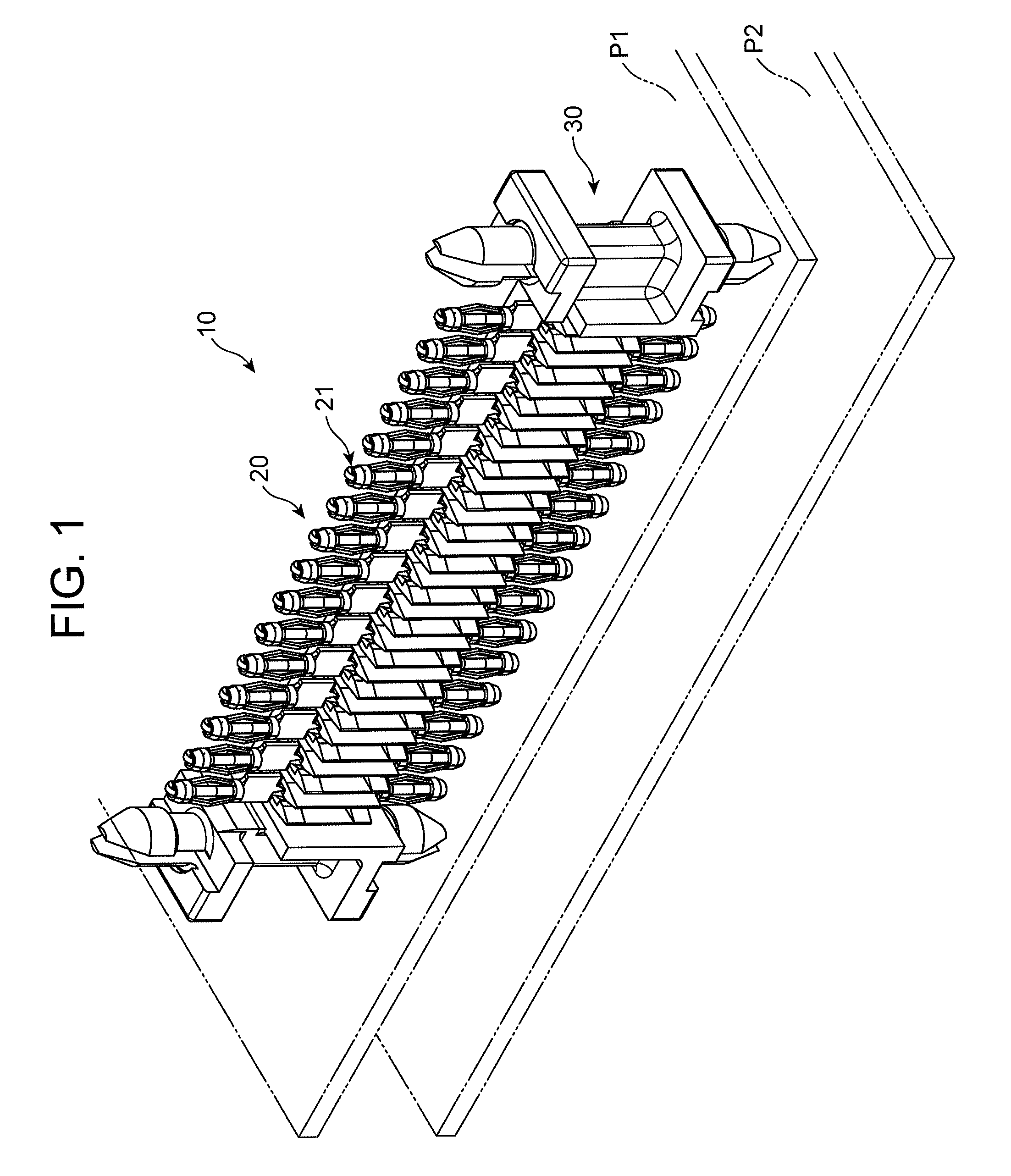
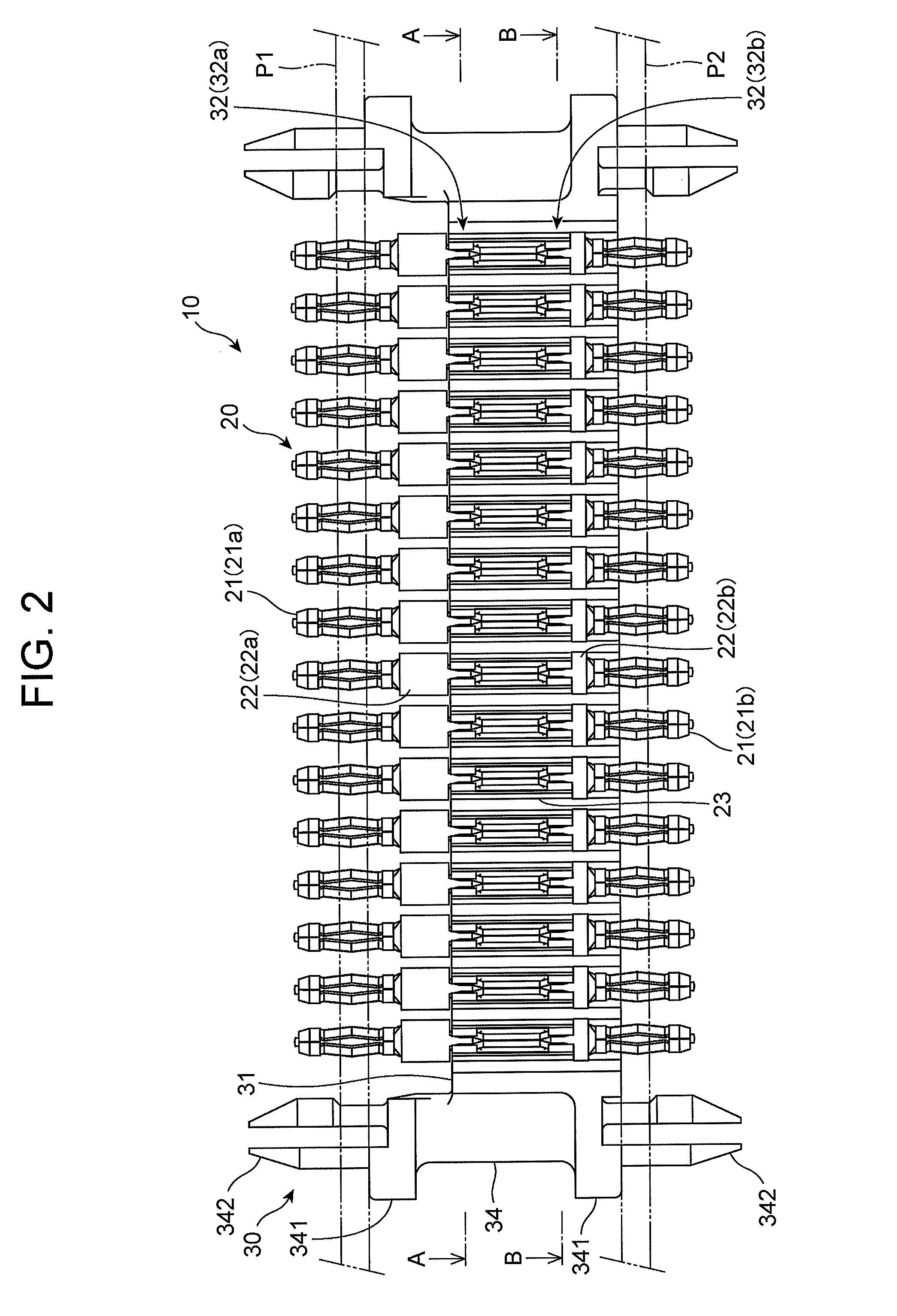
[0067]The electric connector 10 in accordance with the first embodiment, illustrated in FIGS. 1 to 6, is equipped in a vehicle for electrically connecting two printed circuit boards P1 and P2 (see FIG. 2) facing each other.

[0068]The electric connector 10 includes a plurality of connector terminals 20 each in the form of a bar, and a connector housing 30 supporting the connector terminals 20 in a line.

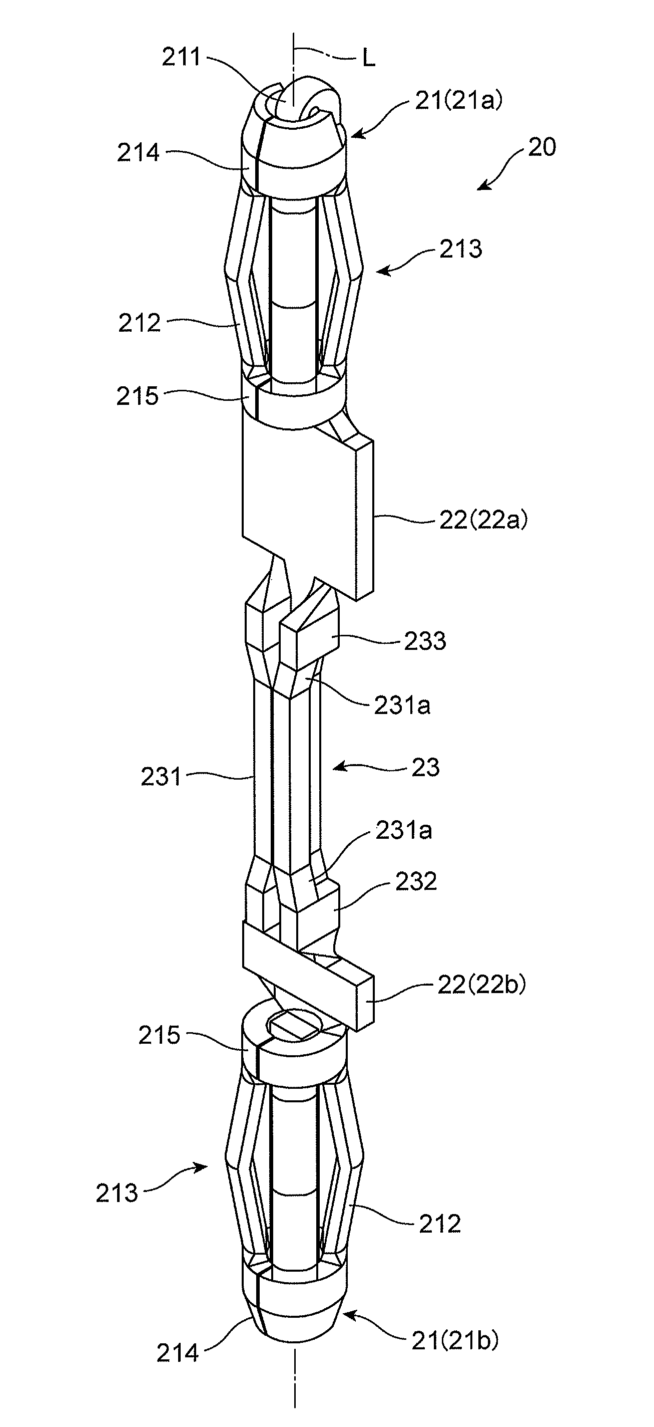
[0069]Each of the connector terminals 20 illustrated in FIGS. 10 to 13 includes first and second press-fit terminals 21a and 21b at opposite ends, first and second projecting portions 22a and 22b restricting the connector terminal 20 in the movement in a length-wise direction of the connector terminal 20, and a buffer portion 23 deformable in accordance with a gap between imaginary longitudinal center lines L of the press-fit terminals 21. ...

second embodiment

[0122]An electric connector in accordance with the second embodiment of the present invention is explained hereinbelow with reference to FIGS. 23 to 26. Parts or elements that correspond to those of the first embodiment have been provided with the same reference numerals, and operate in the same manner as corresponding parts or elements in the first embodiment, unless explicitly explained hereinbelow.

[0123]In an electric connector 20x in accordance with the second embodiment, a second projecting portion 22bx is designed to have the same size as that of a first projection portion 22ax, as illustrated in FIGS. 23 and 24.

[0124]The second projecting portion 22bx is designed to be larger than the second projection portion 22b in the first embodiment (see FIGS. 10 and 11), and to be formed of a thin resilient metal plate having a length longer in a length-wise direction of the connector terminal 20x than a width (a length measured in a width-wise direction of the connector terminal 20x). ...


PUM


Abstract

The connector terminal includes at opposite ends a pair of press-fit terminals to be inserted into through-holes formed through two printed circuit boards located facing each other, each of the press-fit terminals having a plurality of contact pieces, and further includes at least one buffer portion deformable in accordance with a gap between imaginary longitudinal center lines of the press-fit terminals.

Description

BACKGROUND OF THE INVENTION[0001]1. Field of the Invention[0002]The present invention relates to a connector terminal including at opposite ends thereof a pair of press-fit terminals to be inserted into through-holes formed through each of two printed circuit boards located facing each other, to thereby electrically connect the two printed circuit boards to each other. The present invention relates further to a connector housing suitable to the connector terminal.[0003]2. Description of the Related Art[0004]There is known an electric connector holding a plurality of connector terminals in a line. The connector terminals are inserted at one of ends thereof into through-holes formed through a first printed circuit board, and at the other end thereof into through-holes formed through a second printed circuit board, to thereby electrically connect circuits mounted on the first and second printed circuit boards to each other.[0005]FIGS. 27A and 27B illustrate a connector 100 suggested in...

Claims


Application Information

Patent Timeline
Patent Type & Authority Patents(United States)
IPC IPC(8): H01R12/00H01R13/58H05K1/00H01R12/52H01R12/58H01R12/91H01R13/422H01R12/70
CPCH01R13/58H01R12/523H01R12/585H01R12/91H01R13/4226H01R12/7023
Inventor ENDO, TAKAYOSHIYAGI, SAKAITAKEDA, TAKUYA
Owner DAIICHI SEIKO CO LTD
Why Eureka
Try Eureka