
Apparatus and method for generating sensory vibration

a technology of sensory vibration and apparatus, applied in the field of apparatus for generating sensory vibration with a sense of realism, can solve the problems of related art methods that fail to further increase the sense of realism or the realistic sense of 3d games, and are different from real situations

Active Publication Date: 2015-12-22
LG ELECTRONICS INC
View PDF13 Cites 5 Cited by
  • Summary
  • Abstract
  • Description
  • Claims
  • Application Information

AI Technical Summary

Benefits of technology

[0013]Therefore, an aspect of the detailed description is to provide an image display apparatus capable of making a game or a virtual reality seem to be more realistic or vivid, and a method for adjusting a vibration output parameter for implementing a vibration with a sense of realism.
[0034]In accordance with an image display apparatus for outputting a vibration with a sense of realism and an realistic sense and a method for adjusting an intensity of vibration for implementing a vibration with sense of realism and an realistic sense, a user of the image display apparatus can directly recognize (experience) a situation happened on a space formed by a screen by virtue of the vibration with the sense or presence and the realistic sense, output in association with an effect of a displayed image, and also can feel more the sense of realism and the realistic sense from the situation in the game or a virtual reality.

Problems solved by technology

However, the above method generates a vibration output without concerning about the environments of the space formed by the screen displayed, so it may be different from a real situation.
Especially, considering that the latest trend of 3D games is to realize a virtual reality more similar to the real environment, the related art method may fail to further increase the sense of realism or the realistic sense of the 3D games.

Method used


Image

  • Apparatus and method for generating sensory vibration
  • Apparatus and method for generating sensory vibration
  • Apparatus and method for generating sensory vibration

Examples


first exemplary embodiment

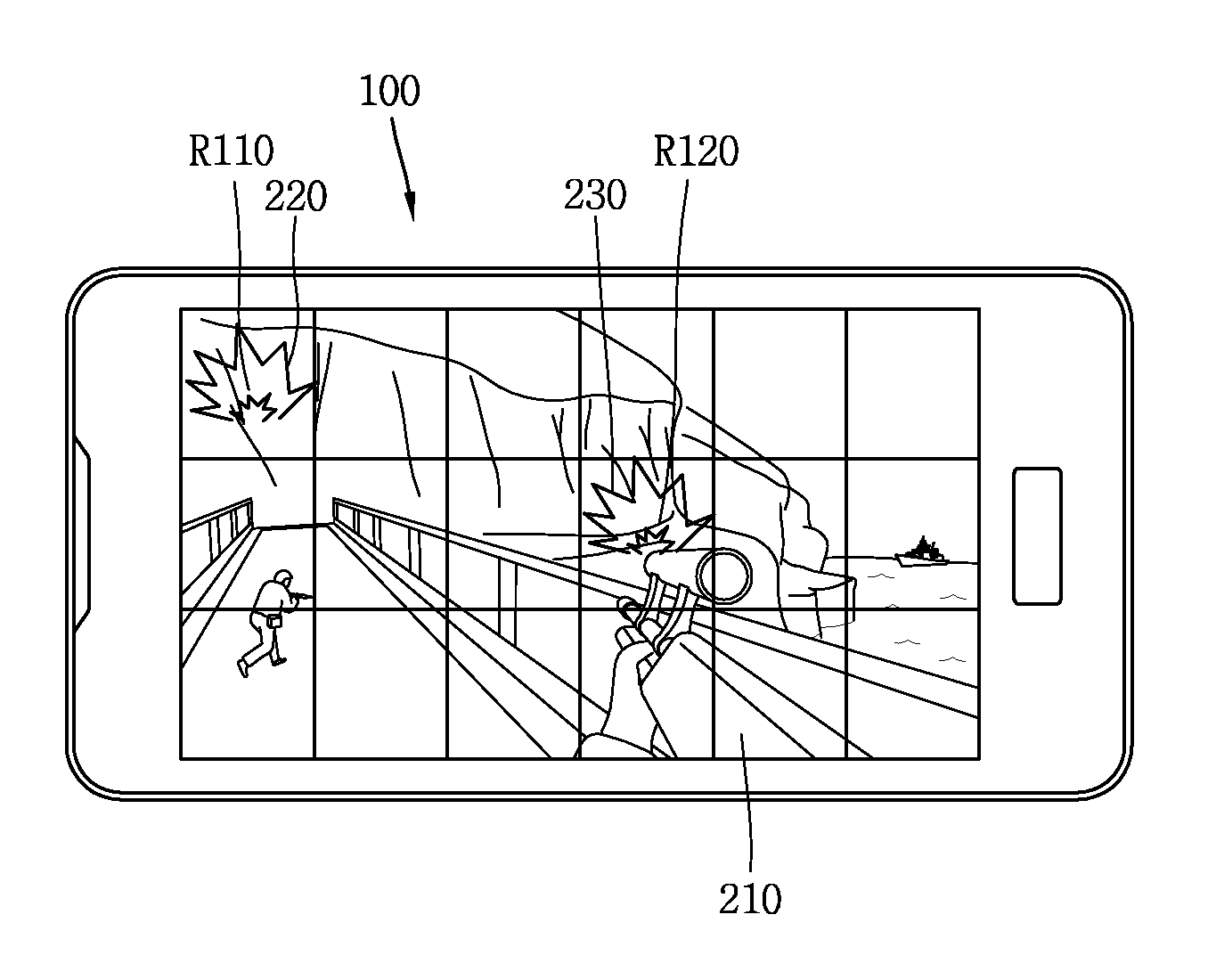
[0101]FIG. 4 is an exemplary view showing a method for determining a vibration output parameter in accordance with a first exemplary embodiment.

[0102]As shown in FIG. 4, a screen displayed by the image display apparatus 100 may have a plurality of regions. Among the plurality of regions, FIG. 4 shows a first region R110 including a first point 220 where a first event is generated, and a second region R120 including a second point 230 where a second event is generated.

[0103]In accordance with the first exemplary embodiment, the image display apparatus 100 may further include a memory (not shown). The memory may store, in form of a table, vibration output parameters corresponding to the plurality of regions.

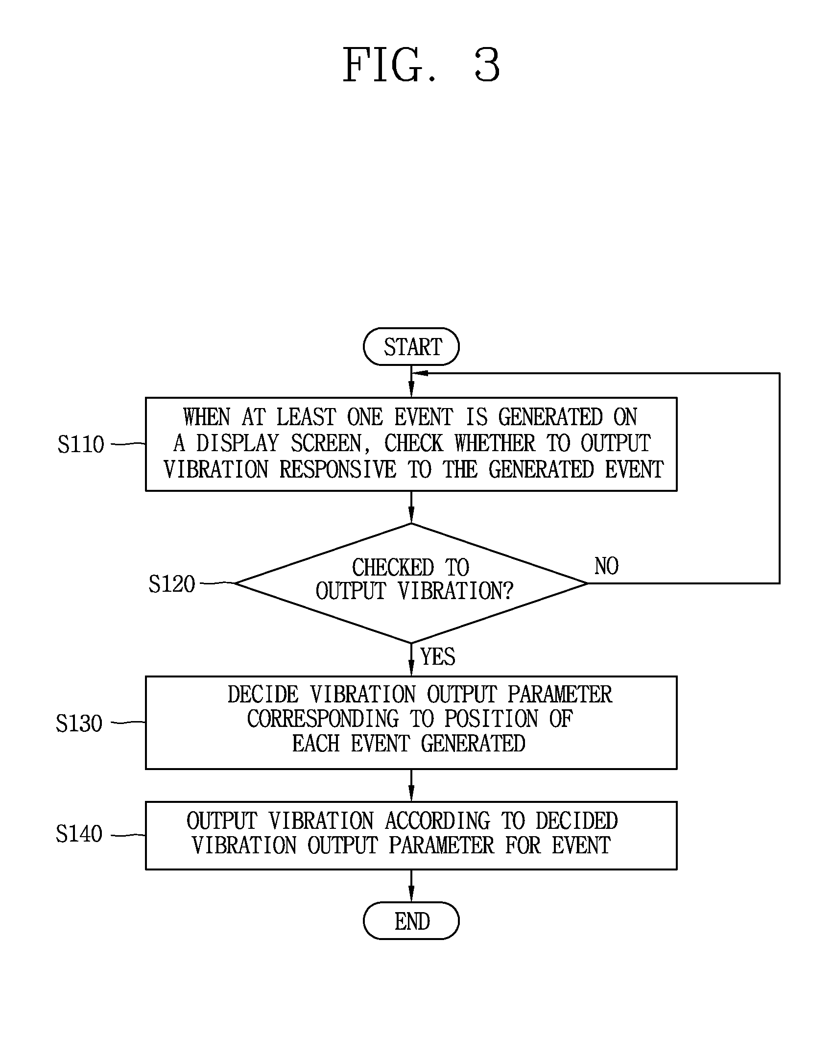
[0104]When the first and second events are generated on the screen, the controller 110 may determine whether to output vibrations for the first and second events.

[0105]When it is determined to output the vibrations for the first and second events, the controller 110 may decide a vi...

second exemplary embodiment

[0107]In accordance with the second exemplary embodiment, the controller 110 may generate a control signal to allow for outputting a vibration corresponding to each event to the outside of the image display apparatus 100.

[0108]As aforementioned, the control signal generated by the controller 110 is transferred to the driving unit 140, and the driving unit 140 may drive the exciter 120 to generate vibration based on the transferred control signal.

[0109]Here, for outputting the vibration corresponding to each event, the controller 110 may decide (select) an intensity of vibration of the a vibration output parameters.

[0110]Hereinafter, description will be given of a method for deciding an intensity of vibration in accordance with a second exemplary embodiment. Also, as one example, description will be given of a process of outputting a 3D space on a screen displayed and deciding an intensity of vibration for each event when at least one event is generated on the 3D space.

[0111]First, w...

third exemplary embodiment

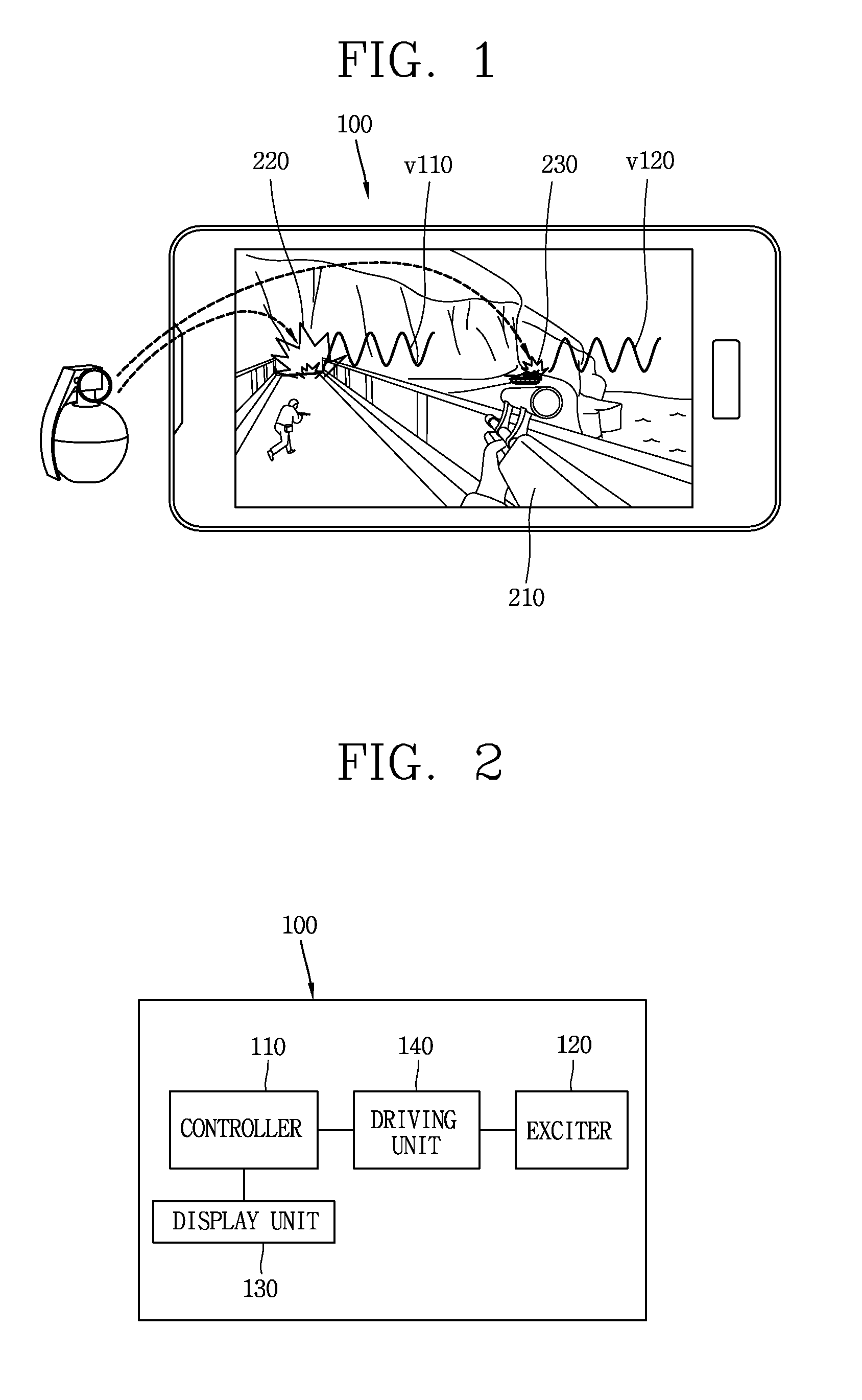
[0129]FIG. 6 is an exemplary view showing an image display apparatus for outputting a vibration with a sense of realism in accordance with a third exemplary embodiment.

[0130]As shown in FIG. 6, for a 3D firing emulation game, a first object 210, which is a user object in a shape of a gun, is substituted on the 3D space output from the image display apparatus 100, and an explosion of a grenade thrown, which is an event generated in the 3D firing emulation game, is occurring respectively at a first point 220 and a second point 230.

[0131]In accordance with a third exemplary embodiment, the image display apparatus 100 may decide intensity of a vibration based on the event-generated point and the user object for output of a realistic vibration effect. In FIG. 6, since the distance between the first point 220 and the first object 210 is shorter than the distance between the second point 230 and the first object 210, the impact of the explosion of the thrown grenade in a real situation may...


PUM


Abstract

In an image display apparatus for outputting a vibration with a sense of realism and an realistic sense and a method for adjusting an intensity of vibration for implementing a vibration with sense of realism and an realistic sense, a user of the image display apparatus can directly recognize (experience) a situation happened on a space formed by a screen by virtue of the vibration with the sense or presence and the realistic sense, output in association with an effect of a displayed image, and also can feel more the sense of realism and the realistic sense from the situation in the game or a virtual reality.

Description

CROSS-REFERENCE TO RELATED APPLICATION[0001]Pursuant to 35 U.S.C §119, this application claims the benefit of earlier filing date and right of priority to Korean Application No. 10-2011-0079279, filed in Republic of Korea on Aug. 9, 2011, the contents of which is incorporated by reference herein in its entirety.BACKGROUND OF THE INVENTION[0002]1. Field of the Invention[0003]This specification relates to an apparatus for generating a vibration with a sense of realism (realistic vibration effect, sensory vibration effect) and a method for adjusting a vibration output parameter for implementing a vibration with a sense of realism, and particularly, to a method for implementing a vibration with a sense of realism, in which a vibration output parameter is adjusted based on an environment or condition of a screen displayed.[0004]2. Background of the Invention[0005]Recently, the growth of an image display apparatus (i.e., display) for displaying images (e.g., two-dimensional (2D) image, th...

Claims


Application Information

Patent Timeline
Patent Type & Authority Patents(United States)
IPC IPC(8): A63F13/40G06F3/01
CPCA63F13/10G06F3/016A63F2300/1037G06F2203/013A63F2300/302A63F2300/64A63F2300/8076A63F2300/204A63F13/92A63F13/285A63F13/837G06F3/14A63F13/40G06T15/10
Inventor BAE, SUNGHO
Owner LG ELECTRONICS INC
Learn More