Circuit switch for keyboard

a circuit switch and keyboard technology, applied in the field of keyboards, can solve the problems of difficult addition or adjustment of other sensitive circuits or grounded circuit layouts, failure to maintain stable and accurately apply the capacitance generated between the first and third membranes, and increase so as to achieve the effect of lowering the complexity of circuit design and capacitive

Active Publication Date: 2015-12-22
SOLID YEAR CO LTD
View PDF18 Cites 0 Cited by
  • Summary
  • Abstract
  • Description
  • Claims
  • Application Information

AI Technical Summary

Benefits of technology

[0007]The primary objective of the present invention is to provide a circuit switch, content and layout of which are flexibly adjustable as per actual needs to lower the complexity of the circuit design and which can accurately and stably detect actions of keys of a keyboard.
[0009]In light of the structure mentioned above, the first and second sensitive portions can keep a fixed interval therebetween from each other, so the capacitive effect generated can be stable to accurately and stably detect the actions of the keys. Besides, mounting the grounded circuit to different positions can make the content and layout of the circuit adjustable as per actual needs, further lowering the complexity of the circuit design.

Problems solved by technology

However, in the process of manufacture of the aforesaid second membrane, burrs or irregular surfaces are subject to formation around the through holes to make the first and third thin membranes fail to keep consistent interval therebetween or make the interval of some area therebetween smaller or larger to further make the capacitance generated between the first and third membranes fail to remain stable and to be accurately applied to detection of actions of the keys.
Besides, electrodes and circuits need to be disposed on the first and third membranes, so it is not easy to add or adjust the layouts of other sensitive circuits or grounded circuits.
In this way, the circuit design becomes more complicated and the size of the whole circuit hardware cannot be effectively reduced.

Method used


Image

  • Circuit switch for keyboard
  • Circuit switch for keyboard
  • Circuit switch for keyboard

Examples


Embodiment Construction

[0024]Structural features and desired effects of the present invention will become more fully understood by reference to four preferred embodiments given hereunder. However, it is to be understood that these embodiments are given by way of illustration only, thus are not limitative of the claim scope of the present invention.

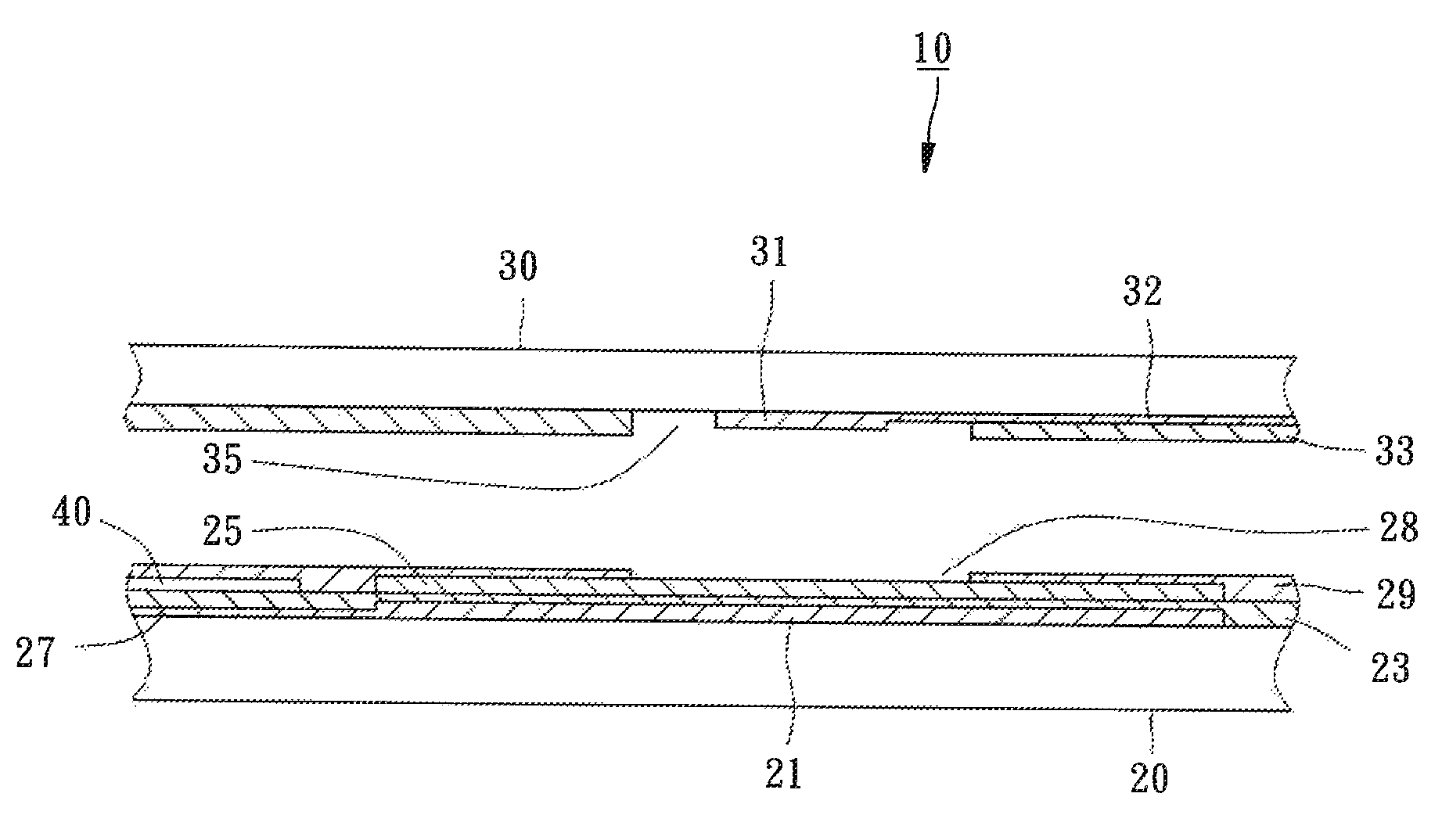
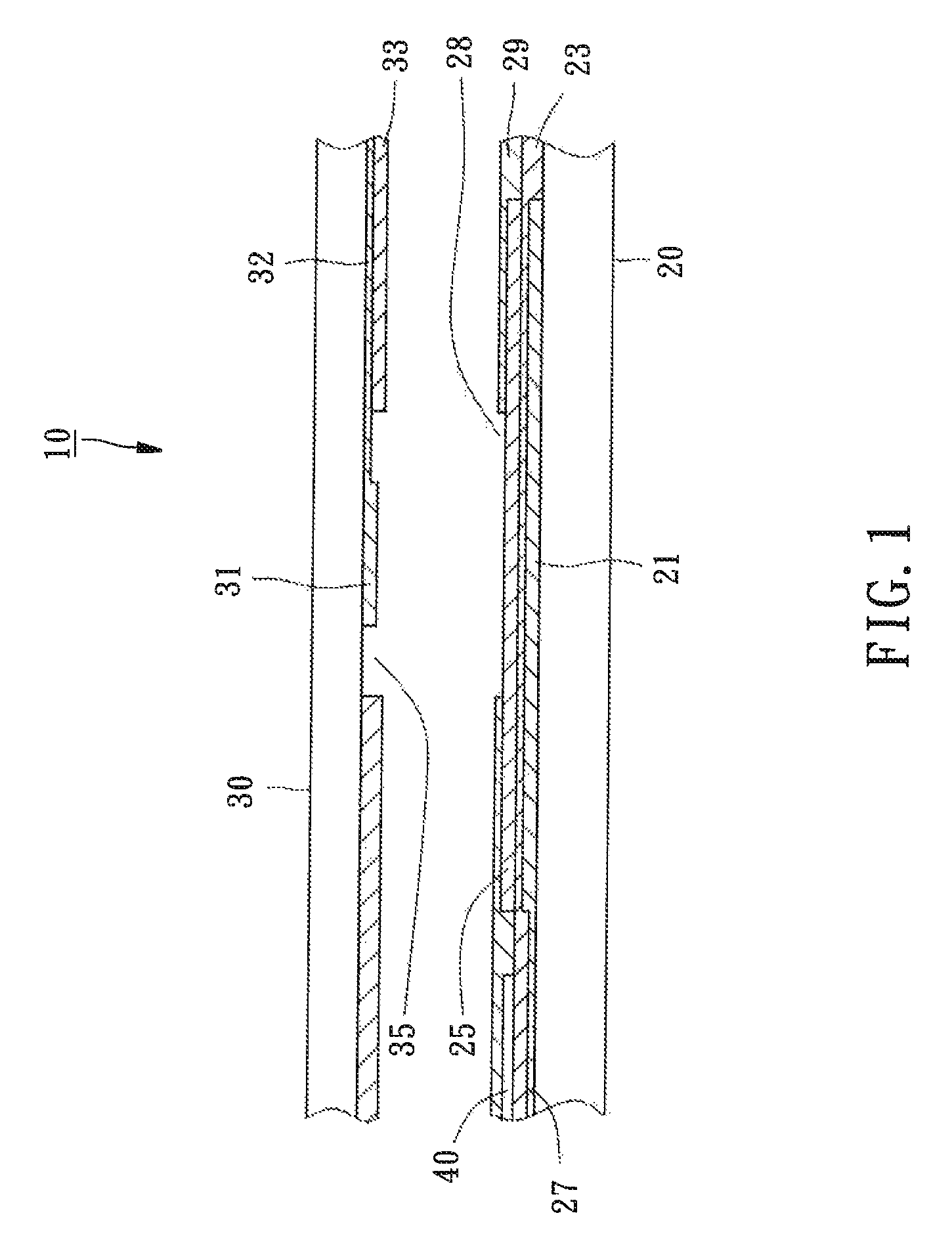
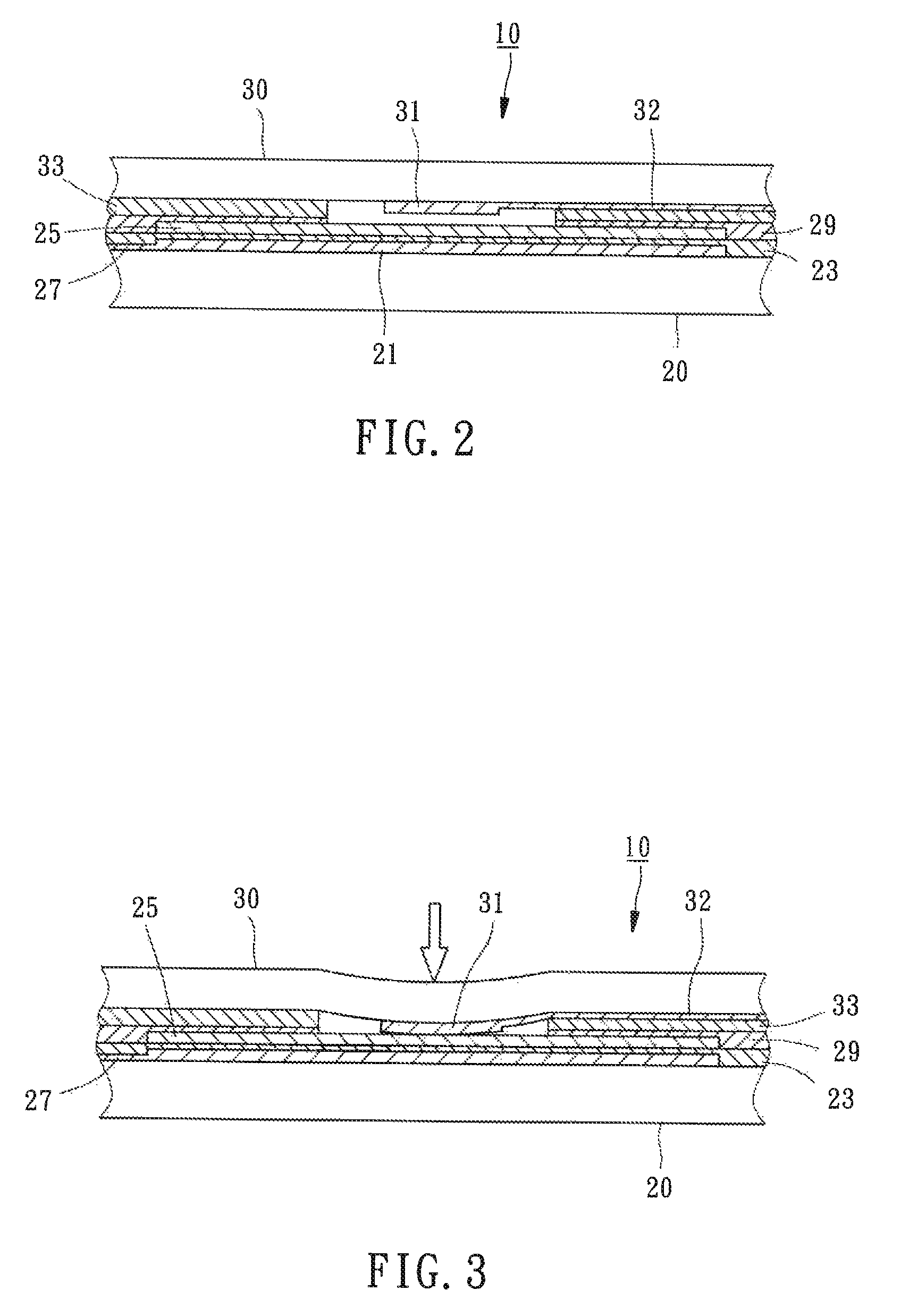
[0025]Referring to FIGS. 1-2, a circuit switch 10 for keys of a keyboard in accordance with a first preferred embodiment of the present invention is formed of a first plate 20 and a second plate 30. Each of the first and second plates 20 and 30 is made of a flexible membrane, such as Mylar®, which can be externally forced to bend. The detailed descriptions and operations of these elements as well as their interrelations are recited in the respective paragraphs as follows.

[0026]A conductive laminated first sensitive portion 21, a laminated first insulated portion 23, and a conductive laminated second sensitive portion 25 are mounted to a top side of the first pla...


PUM


Abstract

A circuit switch for a keyboard is formed of a first plate and a second plate. A first sensitive portion and a second sensitive portion are mounted on a surface of the first plate, superposed on each other, and electrically insulated against each other. A first conductive wire is located on the first plate and electrically connected with the first sensitive portion. A conductive portion is located on the second plate. The second plate is parallel to the first plate in arrangement. The conductive portion corresponds to the second sensitive portion in a way that an interval is located therebetween. A second conductive wire is located on the second plate and electrically connected with the conductive portion. A grounded circuit is located between the first and second plates and spaced from the second sensitive portion. The grounded circuit partially overlaps or crosses the first or second conductive wire.

Description

BACKGROUND OF THE INVENTION[0001]1. Field of the Invention[0002]The present invention relates generally to a keyboard and more particularly, to a circuit switch for a keyboard.[0003]2. Description of the Related Art[0004]To prevent multiple keys of a keyboard from misjudgment while they are pushed to work at the same time, a capacitive circuit board is usually used to serve as the detecting circuit of the keys. For example, U.S. Pat. No. 3,921,167 disclosed a capacitive circuit board, which includes two boards having respective printed circuits and an insulated layer mounted between the two boards. Capacitance can be generated between the printed circuits of the two boards and when the two printed circuits are electrically connected, the electric state of the circuit board can be detected.[0005]Taiwan Pat. No. M377824 disclosed a keyboard membrane circuit board, which includes corresponsive electrodes located at the first and third membranes. Each of the electrodes is connected with...

Claims


Application Information

Patent Timeline
Patent Type & Authority Patents(United States)
IPC IPC(8): H03K17/975
CPCH03K17/975
Inventor LIANG, HUI-HU
Owner SOLID YEAR CO LTD
Why Eureka
Try Eureka