
Method for reducing the movements of light from a movable light source

a technology of moving light and movement, applied in the direction of vehicle components, signalling/lighting devices, optical signalling, etc., can solve the problem of complicated realization of such a driving state detection, and achieve the effect of reducing light movement, simple measurement techniques, and reliable construction

Active Publication Date: 2015-12-29
HELLA KG HUECK & CO
View PDF8 Cites 0 Cited by
  • Summary
  • Abstract
  • Description
  • Claims
  • Application Information

AI Technical Summary

Benefits of technology

The present invention is a method and device for reducing movements of light from a movable light source. The invention aims to achieve quick and precise reductions of light movements that are not corresponding to the road course, and to level out or harmonize the light movements. The technical effect of the invention is to provide a reliable and simple solution for reducing light movements, resulting in improved road safety and visibility.

Problems solved by technology

However, it has proven disadvantageous that the realization of such a driving state detection is very complicated, because many state parameters of the motor vehicle must be known.

Method used


Image

  • Method for reducing the movements of light from a movable light source
  • Method for reducing the movements of light from a movable light source
  • Method for reducing the movements of light from a movable light source

Examples


Embodiment Construction

[0021]In the following detailed description numerous specific details are set forth in order to provide a thorough understanding of the invention. However, it will be understood by those skilled in the art that the present invention may be practiced without these specific details. For example, the invention is not limited in scope to the particular type of industry application depicted in the figures. In other instances, well-known methods, procedures, and components have not been described in detail so as not to obscure the present invention.

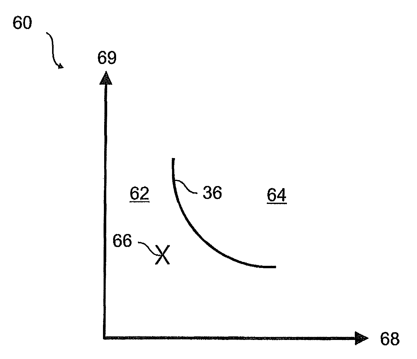
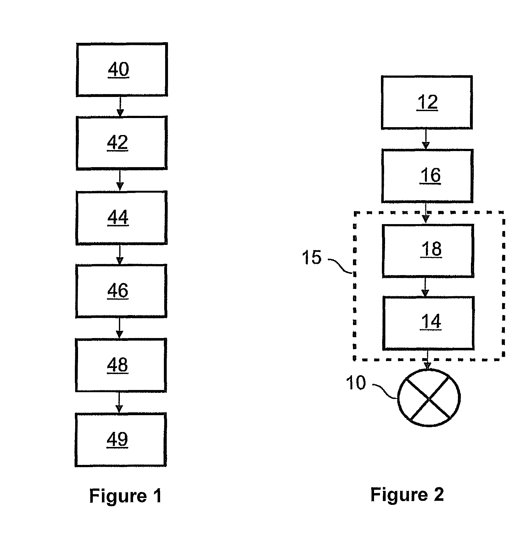
[0022]In FIG. 1, a schematic diagram is shown for detecting light movements that do not correspond to the course of the road. In an initial step 40, the current vehicle steering wheel angle is determined, optionally with filtering. In step 42, steering wheel changes in direction from the vehicle steering wheel angle are detected, for example, by determining the zero crossings of the first derivative of the function of the vehicle steering wheel...


PUM


Abstract

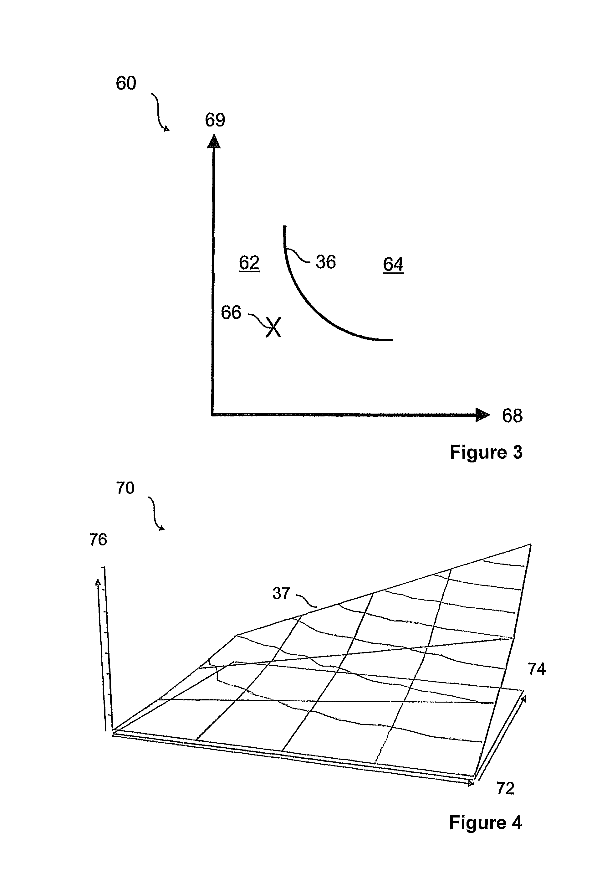
A method for reducing the movements of light from at least one movable light source for a motor vehicle with a steering wheel, wherein a movement of the steering wheel causes a movement of the light source includes the steps of detecting a current steering wheel angle and at least one steering wheel angle change coming from the current steering wheel angle is detected over a defined time window and the steering wheel angle change is summed to form a magnitude, wherein simultaneously a number of steering wheel changes in direction is detected within the defined time window, wherein a characteristic value is allocated to each magnitude and the associated number of changes, wherein a comparison of the characteristic value with a limiting value is performed and a decision is made with reference to the comparison whether additional movement of the light source is carried out.

Description

CROSS REFERENCE[0001]This application claims priority to German Patent Application No. 10 2012 112128.1, filed Dec. 12, 2012.TECHNICAL FIELD OF THE INVENTION[0002]The invention relates to a method for reducing the movements of light from at least one movable light source. Furthermore, the invention also relates to a device for reducing the movements of light from a movable light source. The movement of a light source is understood to be, on one hand, the ability to change the light distribution of the light source, e.g., mechanically by means of a swiveling actuator and, on the other hand, the ability to realize a light distribution of the light source by turning on and off several light sources.BACKGROUND OF THE INVENTION[0003]From DE 10 2007 012 834 A1, a method for realizing a cornering light function of a vehicle headlamp is known, wherein the headlamp can be swiveled essentially about a vertical swivel axis. This makes it possible to adapt the light cone of the headlamp to a co...

Claims


Application Information

Patent Timeline
Patent Type & Authority Patents(United States)
IPC IPC(8): B60Q1/12
CPCB60Q1/122B60Q2300/122
Inventor KRAU.BETA., ANDREASKUBITZA, BORIS
Owner HELLA KG HUECK & CO
Learn More