Device and method for adjusting the lighting of a vehicle in blind curves

a technology for blind curves and vehicles, applied in the direction of lighting support devices, transportation and packaging, etc., can solve the problems that the driver or also the automatic system for avoiding glare oncoming vehicles in the curve may not react sufficiently quickly to adjust the lighting, and the adjustment would not be meaningful

Active Publication Date: 2016-01-05
ROBERT BOSCH GMBH
View PDF55 Cites 21 Cited by
  • Summary
  • Abstract
  • Description
  • Claims
  • Application Information

AI Technical Summary

Benefits of technology

[0007]Furthermore, it may be advantageous that the other road users do not have to be recognized visually (e.g., with the aid of a costly camera) or via other sensors, and therefore a simplified cost-effective system may be demonstrated, which possibly does not include the complete functionality of an automatic high beam controller, but assists the driver in specific, rather difficult situations (as here: inability to see into the curve).
[0011]An adjustment / adaptation of the possibly glaring illumination is advantageously only to be carried out if it actually may not be judged before a curve whether a vehicle is oncoming, which is the case if the curve is not visible. On the other hand, if the curve is visible and a possibly oncoming road user may be recognized in a timely manner using existing systems, no measure must be carried out within the scope of glare avoidance. Rather, in this case the illumination may optionally (automatically) be increased, if necessary without activation by the driver, in order to assist him when negotiating the curve. The risk of greater glare probability with better illumination may be accepted, since the curve is considered to be visible and the driver, like an automatic system, may be able to reduce or avoid the possible glare in a timely manner by adjusting the lighting.
[0022]Instead of completely omitting the adjustment when negotiating an outer curve, a reduced adjustment may also take place, whereby the light is only adjusted to have somewhat less glare, than in the case of complete adjustment, in which if possible no glare at all is to occur. This may represent a possible good compromise between optimum illumination and the probability of subjecting oncoming traffic to glare in consideration of the glare effect which is possible at all.
[0032]The terms of glare or non-glare are not necessarily to be understood as discrete; the glare effect increases with increasing luminosity, however, but, vice versa, also may not be entirely avoided without turning off the light. Glare avoidance may also mean a glare reduction in the present case. Greater illumination is usually accompanied with a higher glare risk; these two factors are therefore generally concurrent. On the one hand, the best possible illumination is to be achieved; on the other hand, glare is to be avoided.
[0037]The visibility of a route section (or a curve) provides a dimension of the probability of a sudden appearance of a road user and therefore a glare probability.

Problems solved by technology

In particular, a driver or also an automatic system for glare avoidance of oncoming vehicles in the curve may not react sufficiently rapidly to adjust the lighting to avoid glare if, e.g., a vehicle in a blind curve suddenly comes “around the corner.” A preventive adjustment is therefore only meaningful in this situation, while in situations in which the curve is visible, such an adjustment would not be meaningful.

Method used


Image

  • Device and method for adjusting the lighting of a vehicle in blind curves
  • Device and method for adjusting the lighting of a vehicle in blind curves
  • Device and method for adjusting the lighting of a vehicle in blind curves

Examples


Embodiment Construction

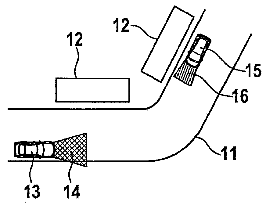
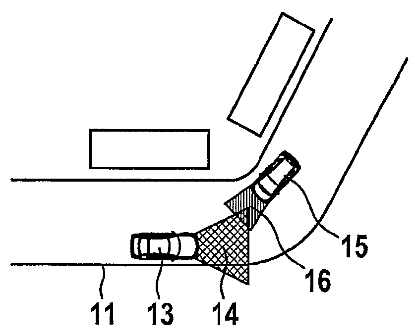
[0044]FIG. 1a shows a scenery of a road 11, in which one's own vehicle 13 is located, which emits a light cone 14 with high beam light and may not yet see, because of vision-obstructing building 12, that another vehicle 15 having a (in the illustrated case) low-beam light cone 16 is oncoming. If the vehicles move toward one another, at a later point in time, as shown in FIG. 1b, the light cone of the high beam light of one's own vehicle 14 will subject the vehicle or the driver of vehicle 15 to glare.

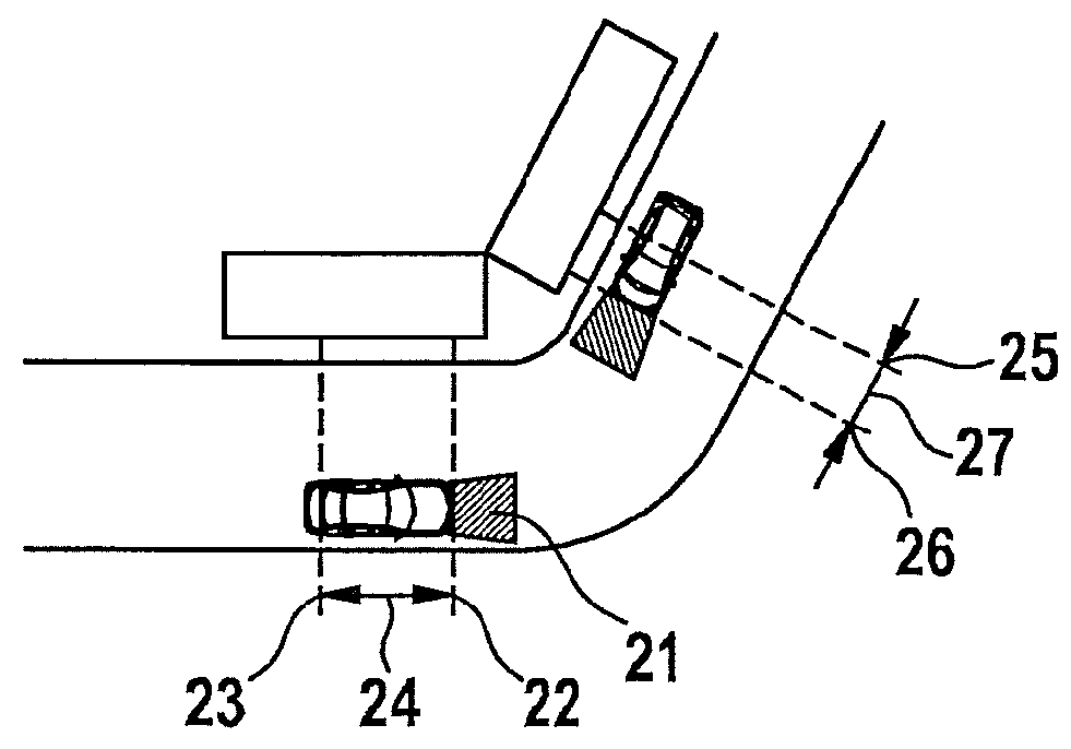
[0045]FIG. 2 describes how the method remedies the problem from FIG. 1. At a location point 23, the high beam light of one's own vehicle is already deactivated for this purpose, this point 23 being located at a configurable distance 24 before the apex or starting point of curve 22. At point 23, the high beam light is switched over to low beam light 21. The high beam light may be reactivated or the adjustment may be canceled out already before the end of curve 25 at a configurable distan...


PUM


Abstract

Method and device for adjusting lighting for a vehicle in consideration of the visibility of a curve, light having a glare effect (high beam light) being deactivated before negotiating a curve, if the curve is not visible, or optionally the illumination being increased if the curve is visible. Adjusting the lighting, in particular of headlights, for a vehicle having a first step, in which an upcoming curve is recognized, its visibility is ascertained, the visibility representing the possibility of glare, in particular to other road users, in particular to oncoming traffic, and a second step, of adjusting the lighting between the least possible glare and the best possible illumination, characterized in that the adjustment is carried out as a function of the visibility.

Description

FIELD OF THE INVENTION[0001]The present invention is directed to a device or method for adjusting the lighting of a vehicle in blind curves according to the definition of the species in the independent claims.BACKGROUND INFORMATION[0002]A light control system is discussed in JP 2004098819 A, which recognizes road conditions and, in the case of a curving road, checks whether the head lights are switched to high beam light, in order to adjust them to low beam light in this case.[0003]A system for light control and glare monitoring is known from US 2002080617 A, the lighting being adapted as a function of the area in which the vehicle is located and as a function of the road course. The lighting is adjusted as a function of the probability with which the vehicle is located in a specific area or before a specific road course.[0004]The generally known problems of vehicle lighting are that, on the one hand, the driver of the vehicle wishes to achieve the best possible illumination for rea...

Claims


Application Information

Patent Timeline
Patent Type & Authority Patents(United States)
IPC IPC(8): B60Q1/00B60Q1/14B60Q1/08B60Q1/04F21V21/29F21V21/28
CPCB60Q1/04B60Q1/085B60Q1/143B60Q2300/42B60Q2300/112B60Q2300/23B60Q2300/322
Inventor NORDBRUCH, STEFAN
Owner ROBERT BOSCH GMBH
Why Eureka
Try Eureka