Snorkel intake dirt inertial separator for internal combustion engine

a technology of dirt inertial separator and internal combustion engine, which is applied in the direction of machine/engine, combustion-air/fuel-air treatment, and separation process, etc., can solve the problems of not providing a practical solution, the air cleaner reaching capacity, and the engine problems of mining vehicles, etc., to achieve the effect of practicality, efficiency and cost-effectiveness

Active Publication Date: 2016-01-12
FORD GLOBAL TECH LLC
View PDF16 Cites 22 Cited by
  • Summary
  • Abstract
  • Description
  • Claims
  • Application Information

AI Technical Summary

Benefits of technology

[0005]The disclosed invention overcomes the problems of known contaminant separators by providing an integrated snorkel intake inertial separator that removes dust and dirt contaminants from the engine intake system prior to reaching the air cleaner in a practical, efficient and cost-effective manner.

Problems solved by technology

Motor vehicles are required to operate in a number of environments that contain many undesirable contaminants, such as dust, dirt, and water that are problematic for internal combustion engines.
In extreme environments, these contaminants are ingested into the air cleaner and can result in the air cleaner reaching capacity by the saturation of contaminants well before the scheduled service interval.
For example, vehicles operating in the mining sector experience engine problems despite their service intervals being reduced for vehicles.
These chambers need to be emptied between service intervals and thus do not provide a practical solution to the problem created by incoming, contaminant-laden air.
Furthermore, as aftermarket systems, these snorkel designs prohibit integration into the snorkel system without significant modification to the snorkel design and vehicle aesthetics.

Method used


Image

  • Snorkel intake dirt inertial separator for internal combustion engine
  • Snorkel intake dirt inertial separator for internal combustion engine
  • Snorkel intake dirt inertial separator for internal combustion engine

Examples


Embodiment Construction

[0023]In the following figures, the same reference numerals will be used to refer to the same components. In the following description, various operating parameters and components are described for different constructed embodiments. These specific parameters and components are included as examples and are not meant to be limiting.

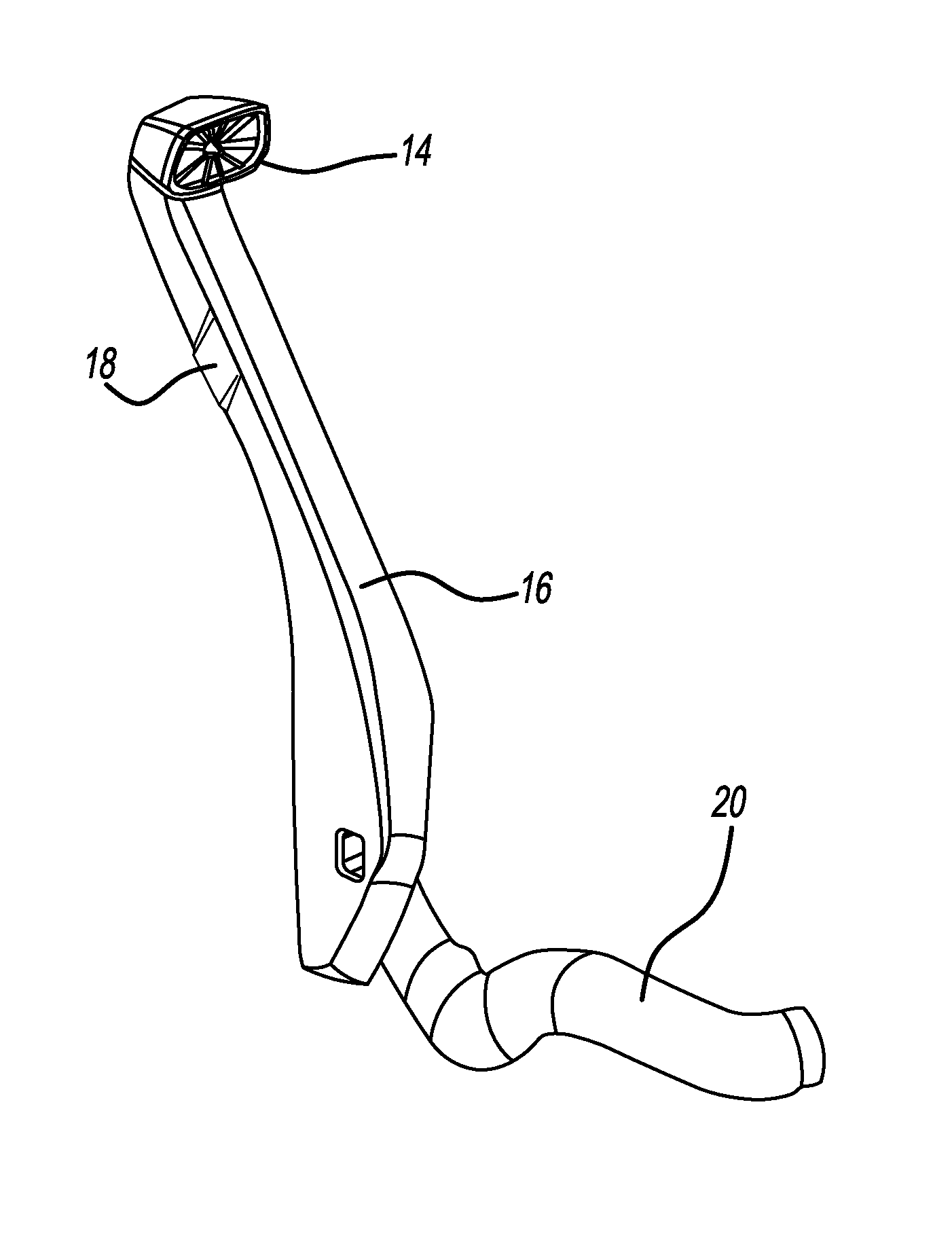
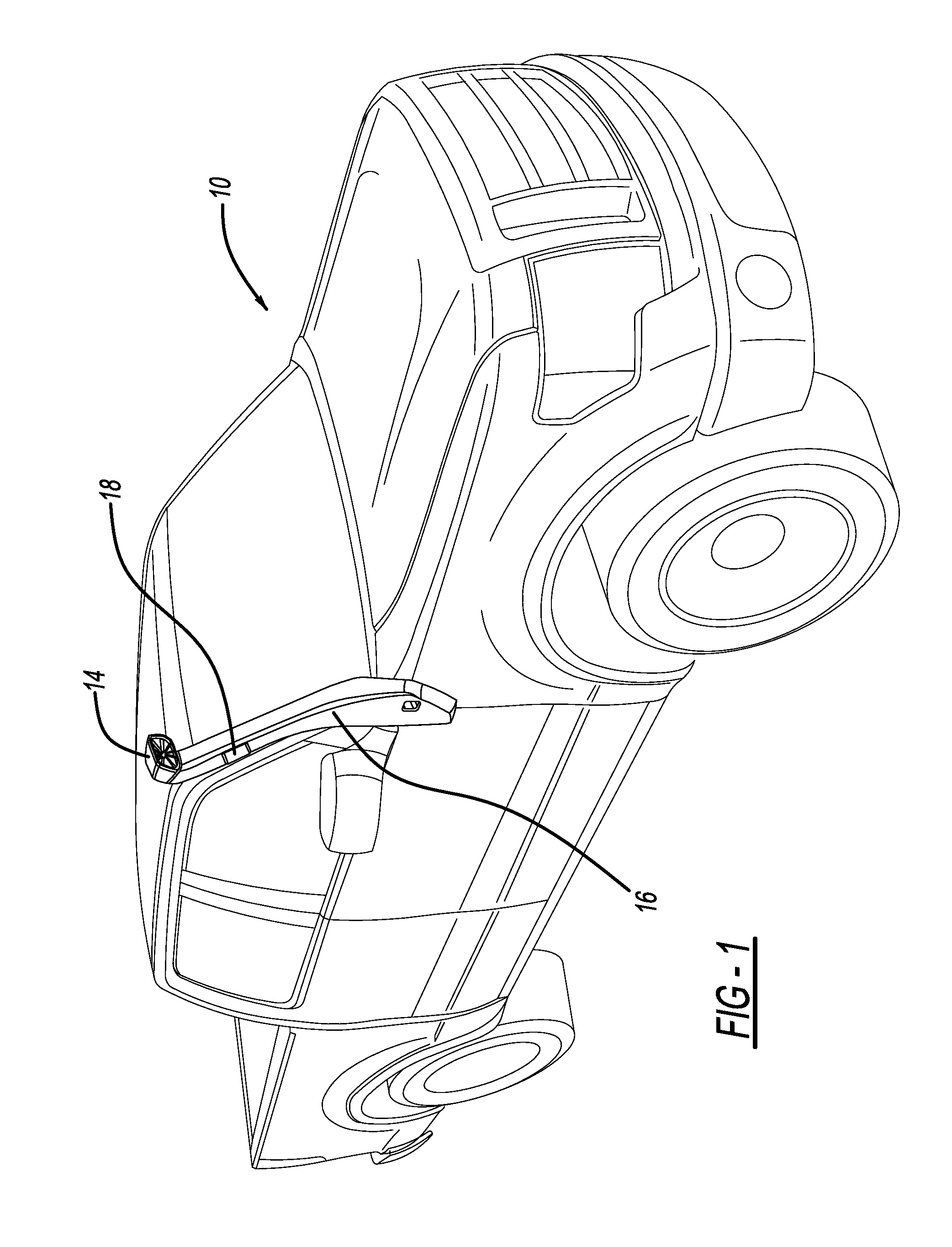
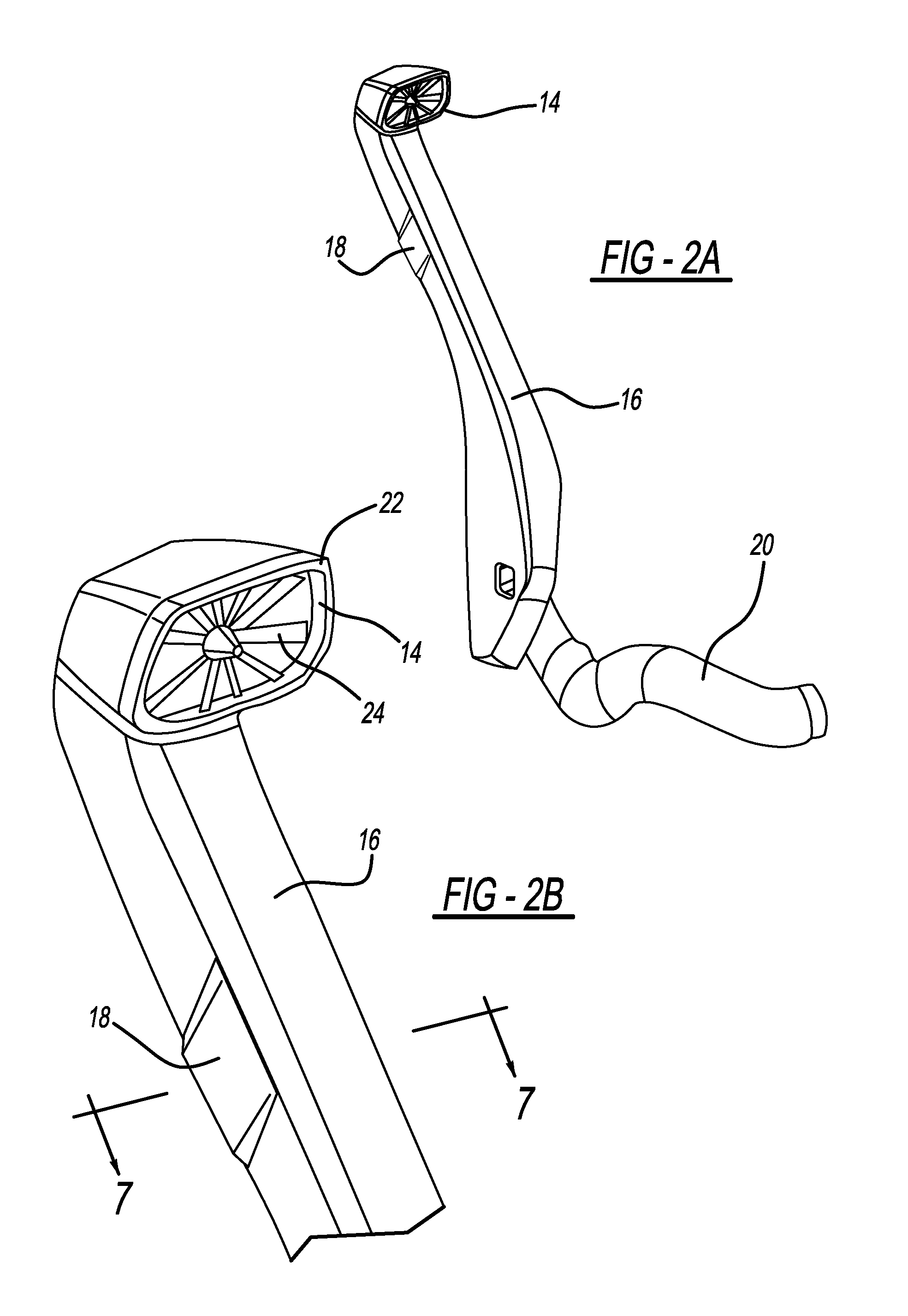
[0024]In general, the disclosed inventive concept provides an integrated snorkel intake inertial separator to remove dust and dirt contaminants from the engine intake system prior to reaching the air cleaner. The snorkel intake inertial separator can find broad application in a variety of vehicles including, as a non-limiting example, the vehicle shown in FIG. 1, generally illustrated as 10. The vehicle 10 is of the sports-utility vehicle type but the snorkel intake inertial separator of the disclosed inventive concept, shown in FIG. 1 as element 12, may also be used on trucks and specialty vehicles, such as mining or military vehicles, and particularly has...


PUM

PropertyMeasurementUnit
durabilityaaaaaaaaaa
gravityaaaaaaaaaa
pressureaaaaaaaaaa

Abstract

An integrated snorkel intake inertial separator is provided to remove dust and dirt contaminants from the engine intake system prior to reaching the air cleaner. The snorkel initiates a cyclonic motion at the snorkel inlet that propagates downstream in a downpipe towards the air cleaner. The cyclonic motion is initiated by radial stators mounted in one embodiment in the snorkel inlet cap or, alternatively, further down the throat of the downpipe. The contaminants in the intake flow are transported radially outwards by the cyclonic motion and are then expelled via a series of extraction ducts formed in the snorkel downpipe. The extraction vents are perpendicular to the cyclonic flow allowing dirt, dust and water particles to be extracted by means of cyclonic motion and gravity. The exit slots are located in regions of low pressure generated by the external aerodynamic airflow around the snorkel.

Description

TECHNICAL FIELD[0001]The disclosed inventive concept relates generally to air filtration systems for internal combustion engines for vehicles. More particularly, the disclosed inventive concept relates to snorkel intake systems for such engines that remove dust and dirt contaminants from the engine intake system prior to reaching the air cleaner.BACKGROUND OF THE INVENTION[0002]Motor vehicles are required to operate in a number of environments that contain many undesirable contaminants, such as dust, dirt, and water that are problematic for internal combustion engines. In extreme environments, these contaminants are ingested into the air cleaner and can result in the air cleaner reaching capacity by the saturation of contaminants well before the scheduled service interval. For example, vehicles operating in the mining sector experience engine problems despite their service intervals being reduced for vehicles.[0003]Known snorkel systems with pre-cleaning technology are typically of ...

Claims


Application Information

Patent Timeline
Patent Type & Authority Patents(United States)
IPC IPC(8): B01D45/12B60K13/02F02M35/022
CPCF02M35/0226B60K13/02F02M35/048F02M35/08F02M35/10013F02M35/164
Inventor LEWINGTON, NEIL PAULOLIVEIRA, RODRIGO MENDES
Owner FORD GLOBAL TECH LLC
Why Eureka
Try Eureka