Air pump for measuring an air pressure

a technology of air pressure and air pump, which is applied in the direction of positive displacement liquid engines, instruments, machines/engines, etc., can solve the problems of small scale, difficult to clearly recognize the scale when read from a distance, and difficult to achieve the demand of fine goods, etc., to achieve the effect of improving the conventional appearance and high value meri

Active Publication Date: 2016-01-19
BETO ENG & MARKETING
View PDF12 Cites 10 Cited by
  • Summary
  • Abstract
  • Description
  • Claims
  • Application Information

AI Technical Summary

Benefits of technology

[0019]1. The scale plate of the present invention is directly defined on the top surface of the base for directly displaying the air pressure value on the top surface of the base, which can improve the conventional conspicuous appearance and prevent the base from being too thick or too heavy, thereby attaining a high-value merit of fine goods.
[0020]2. The bottom side of the cylinder of the present invention is correspondingly fixed to the scale plate, and the scale plate is disposed at the top surface of the base, which allows the area of the scale plate to be closed to the area of the top surface of the base. Therefore, the area of the scale plate is much bigger than the conventional scale plate, which allows the scale to be clearly recognized when read from a distance.

Problems solved by technology

1. The conventional variometer is disposed at an outer side of the base, which renders the appearance of the product quite unusual, occupies the space and has difficulty in storing. Furthermore, it may easily cause harmful impact when carrying, so it is hard to achieve the demand of fine goods.
2. The conventional variometer is not adapted to a design with a bigger dimension since the problems of occupying the space and ease of carrying will become severe, which results in a variometer with a quite small scale that makes it difficult to clearly recognize the scale when read from a distance.

Method used


Image

  • Air pump for measuring an air pressure
  • Air pump for measuring an air pressure
  • Air pump for measuring an air pressure

Examples


Embodiment Construction

[0038]Before describing the invention in detail, it should be noted that like elements are denoted by similar reference numerals throughout the disclosure.

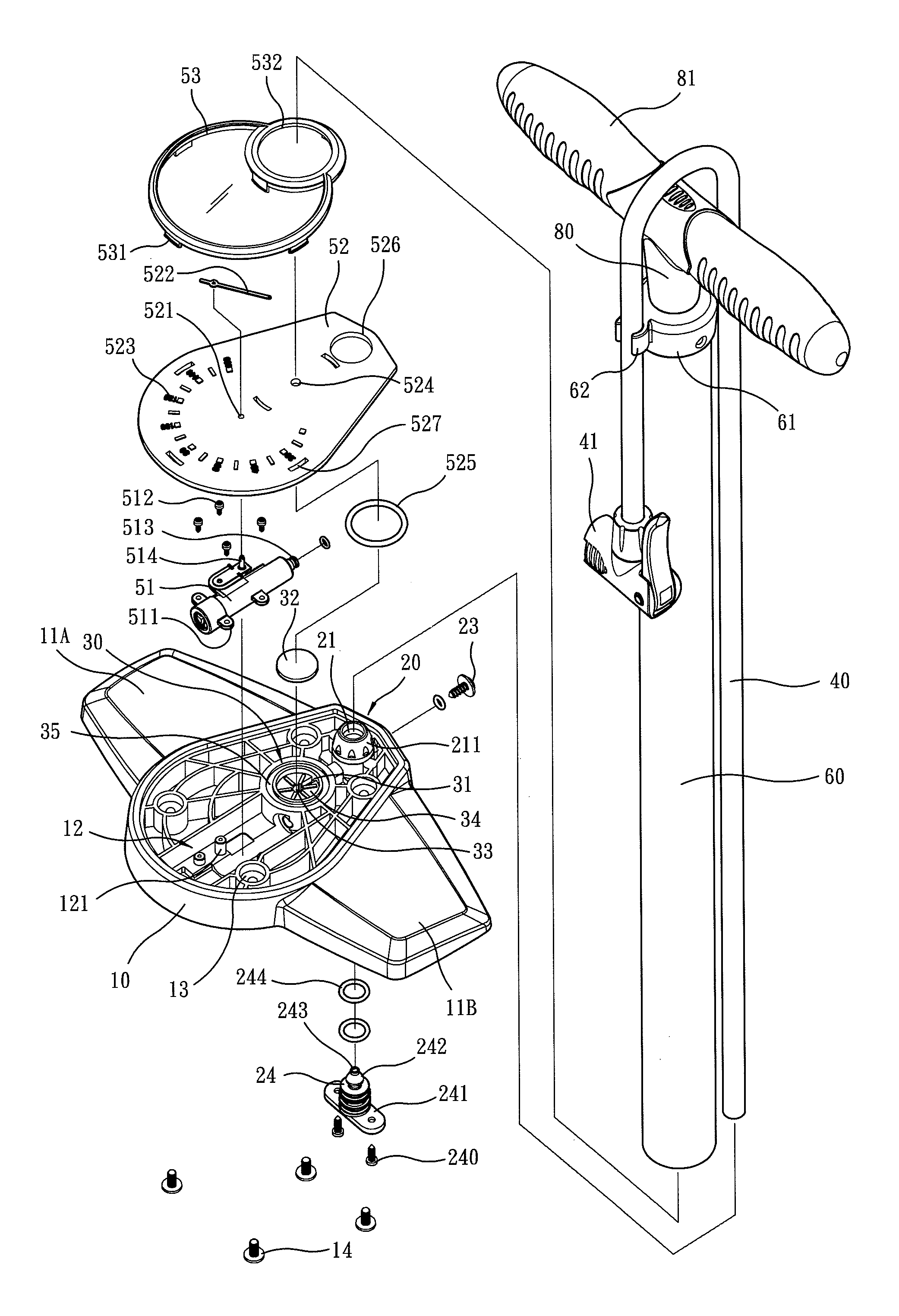
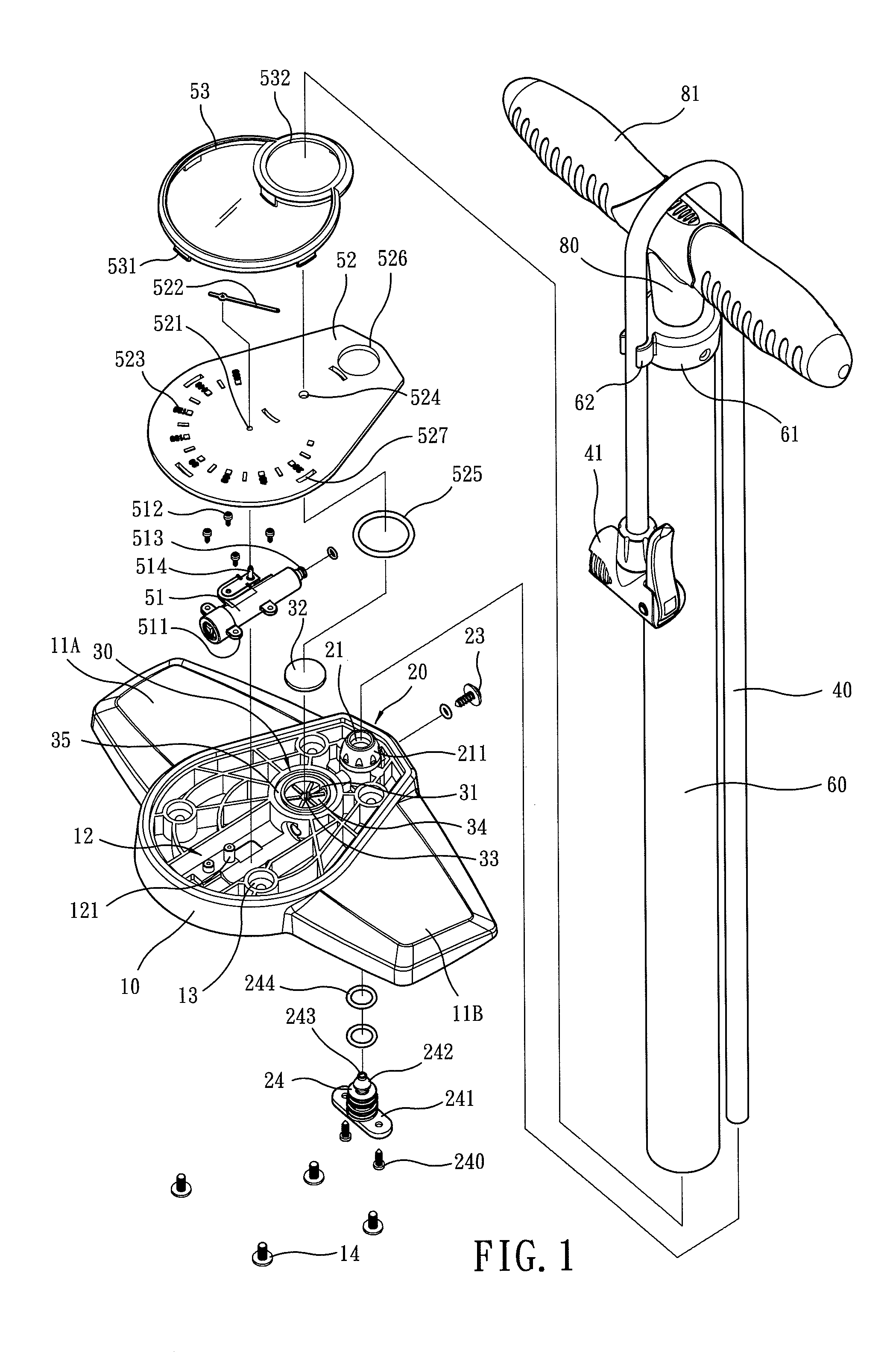
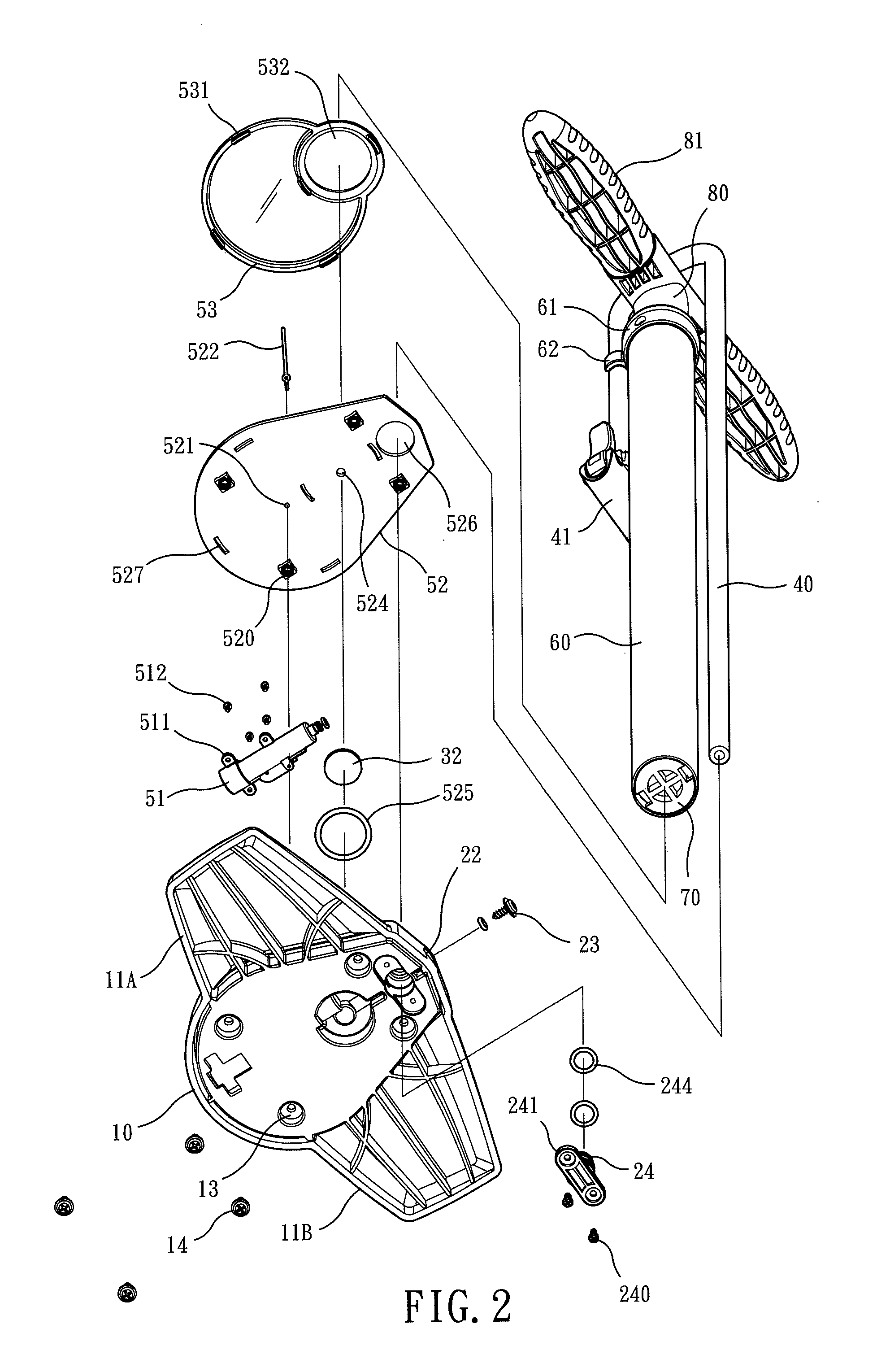
[0039]Referring to FIGS. 1 to 6, the present invention comprises:

[0040]A base 10 includes two pedals 11A, 11B symmetrically protruding at both sides thereof, and a chamber room 12 recessing downward from a top surface of the base 10. The inner side of the chamber room 12 includes a plurality of first base screws 121. Four second base screws 13 are disposed on the base 10. The second base screws 13 provide a second bolt 14 to penetrate through and position from the bottom to the top.

[0041]A pipe-joint section 20 is disposed at the front edge of the base 10, including a longitudinal hole 21, a joint hole 22, a fastener 23, and a joint 24. The longitudinal hole 21, formed by an upper section with a smaller diameter and a lower section with a larger diameter, penetrates through the base 10. A collar unit 211, protruding from the top s...


PUM

PropertyMeasurementUnit
air pressureaaaaaaaaaa
pressureaaaaaaaaaa
air pressuresaaaaaaaaaa

Abstract

An air pump that measures an air pressure including a base, a one-way valve, a pump pipe, a piezometer, a scale plate, a cylinder, a piston, and a driving stem. The base has a chamber room. The one-way valve has an inlet chamber and a vent. The scale plate has an air-guiding hole so that a cylinder hole of the cylinder is communicated with the air-guiding hole. A piston is driven to pump gas in the cylinder hole, thereby forcing the gas to enter the inlet chamber, rendering the vent to deliver the gas unidirectionally, and allowing the scale plate to display an air pressure value.

Description

BACKGROUND OF THE INVENTION[0001]1. Field of the Invention[0002]The present invention relates to an air pump with a scale plate integrally disposed on the top surface of the base of the pump tube, in particular to a scale plate for measuring the air pressure.[0003]2. Description of the Related Art[0004]The newest technique of disposing the variometer on the base of an air pump is disclosed by FIG. 1 of Taiwan patent number I304454 whose title is “An air pump capable of varying in three kinds of air pressure” and FIG. 1 of Taiwan Utility Innovation number M410797 whose title is “An air pump put on the ground”.[0005]However, the variometers of the prior patents have disadvantages as follows:[0006]1. The conventional variometer is disposed at an outer side of the base, which renders the appearance of the product quite unusual, occupies the space and has difficulty in storing. Furthermore, it may easily cause harmful impact when carrying, so it is hard to achieve the demand of fine good...

Claims


Application Information

Patent Timeline
Patent Type & Authority Patents(United States)
IPC IPC(8): F04B33/00G01L23/10G01L11/02F04B39/00
CPCF04B33/005F04B39/00G01L11/025G01L23/10
Inventor WANG, LOPIN
Owner BETO ENG & MARKETING
Why Eureka
Try Eureka