Method of calibrating torque using peak hold measurement on an electronic torque wrench

a technology of electronic torque wrenches and peak hold measurement, which is applied in the direction of wrenches, screwdrivers, instruments, etc., can solve the problems of unintended disengagement of components, damage to components or threaded fasteners, and difficulty in disengaging components

Active Publication Date: 2016-01-26
SNAP ON INC
View PDF7 Cites 46 Cited by
  • Summary
  • Abstract
  • Description
  • Claims
  • Application Information

AI Technical Summary

Benefits of technology

[0009]The disclosed tool, calibration fixture, and method of calibration each allows for the adjustment of the torque wrench when no torque is being applied to the torque wrench and eliminates the need to continuously adjust the applied torque while also adjusting the measured reading on the torque wrench.

Problems solved by technology

Under-tightening the components could result in unintended disengagement of the components.
Over-tightening the components could make disengaging the components difficult or could cause damage to the components or the threaded fasteners.
However, the amount of torque applied may drift due to the manual application of the torque.
This causes the applied torque reading of the calibration fixture to drift, which requires continual manual adjustment of the applied torque to maintain a constant reading on the calibration fixture while also adjusting the measured reading on the torque wrench.

Method used


Image

  • Method of calibrating torque using peak hold measurement on an electronic torque wrench
  • Method of calibrating torque using peak hold measurement on an electronic torque wrench
  • Method of calibrating torque using peak hold measurement on an electronic torque wrench

Examples


Embodiment Construction

[0017]While this invention is susceptible of embodiments in many different forms, there is illustrated in the drawings, and herein described in detail, an embodiment of the invention with the understanding that the present disclosure is to be considered as an exemplification of the principles of the invention and is not intended to limit the broad aspect of the invention to embodiments illustrated.

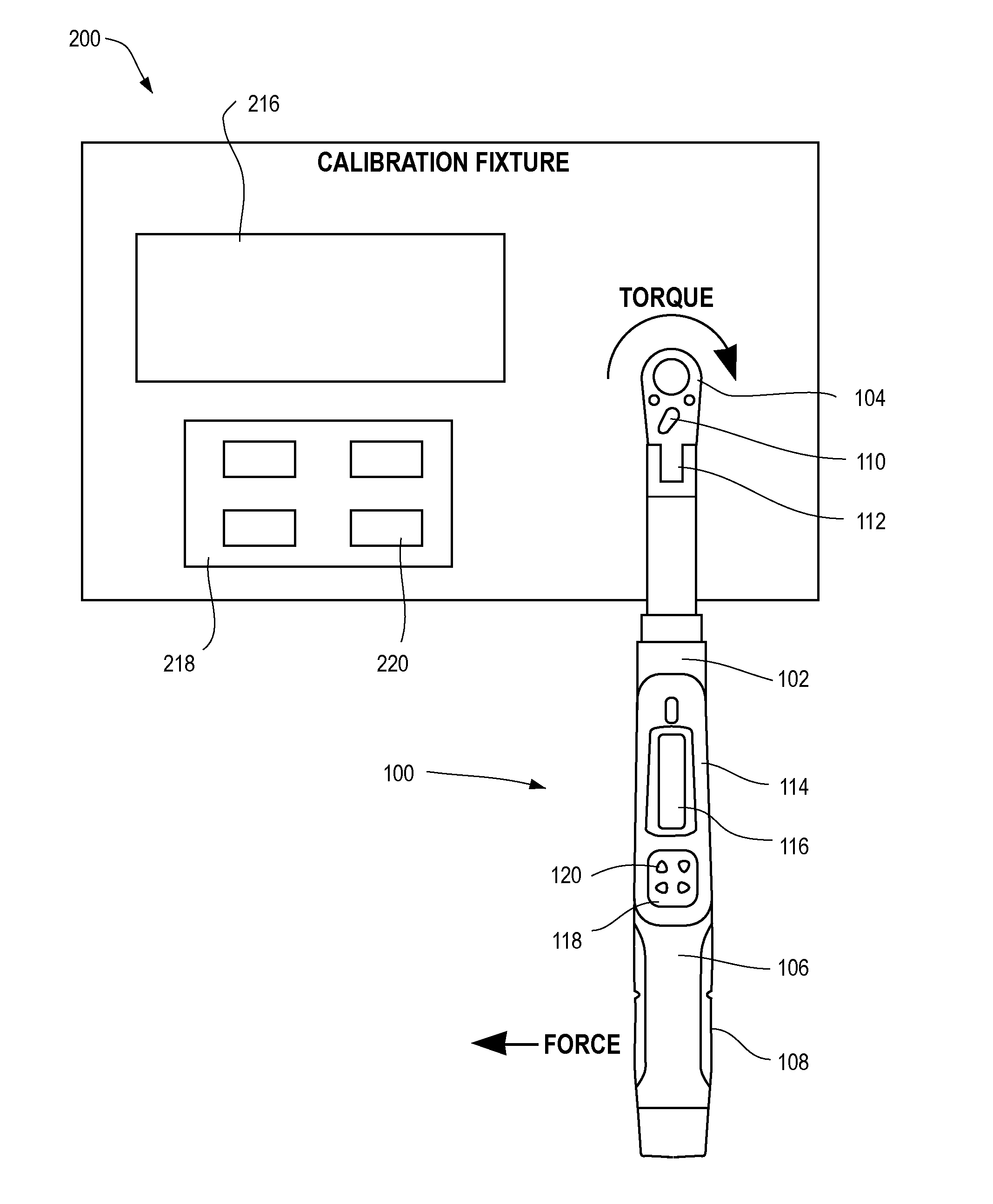
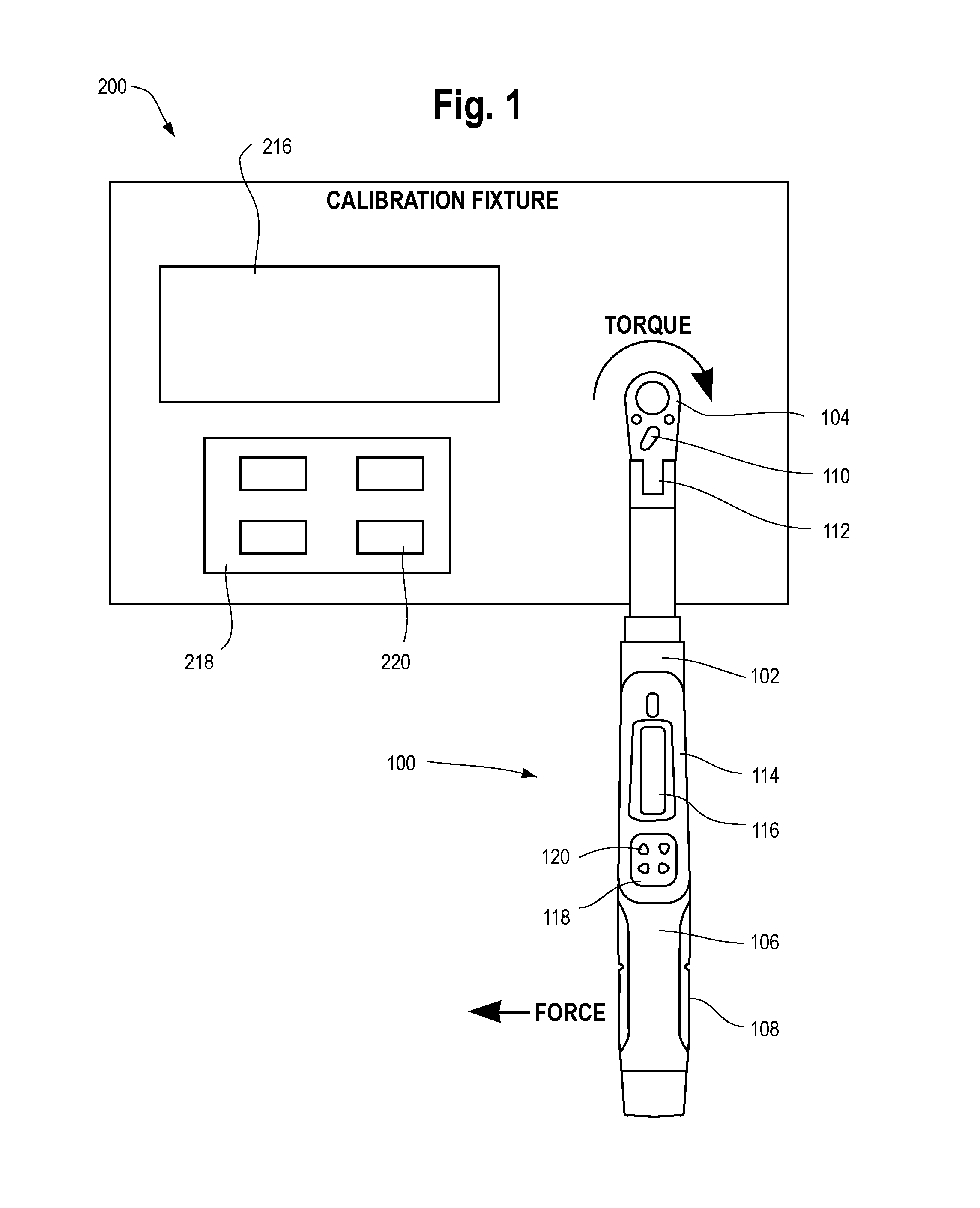
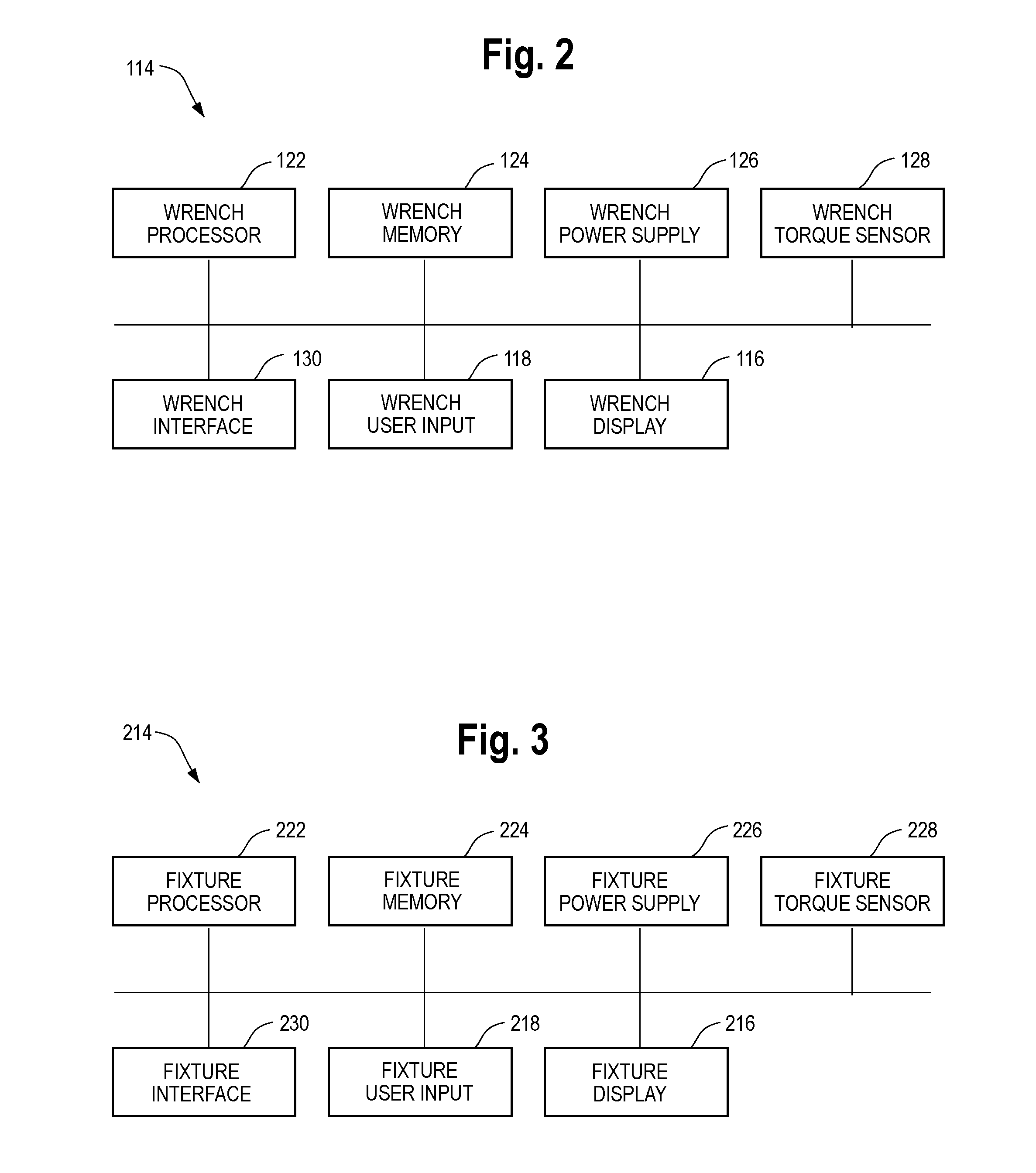
[0018]The present application discloses an electronic torque tool and a calibration fixture, and a method for calibrating the electronic torque tool. The calibration includes the torque wrench applying an amount of torque and releasing the applied torque once the applied torque reaches a full scale calibration torque. The calibration fixture holds and displays a peak value of the applied torque and the torque wrench holds and displays a measured peak value of the applied torque. If the calibration fixture and the torque wrench show different measured amounts of torque, then the measured pe...


PUM

PropertyMeasurementUnit
torqueaaaaaaaaaa
forceaaaaaaaaaa
applied torqueaaaaaaaaaa

Abstract

The present disclosure relates to an electronic torque tool, a calibration fixture, and a method for calibrating the electronic torque tool. The calibration includes applying a torque to the torque wrench and releasing the applied torque once the applied torque reaches a full scale calibration torque. The calibration fixture holds and displays a peak value of the applied torque and the torque wrench holds and displays a measured peak value of the applied torque. The measured peak value on the torque wrench may then be adjusted, by incrementing or decrementing the displayed value, to match the peak value displayed on the calibration fixture.

Description

TECHNICAL FIELD OF THE INVENTION[0001]The present application relates to tools for applying torque to a work piece. More particularly, the present application relates to systems and methods for calibrating electronic torque wrenches.BACKGROUND OF THE INVENTION[0002]Electronic torque wrenches are commonly used in automotive and industrial applications to apply a predetermined amount of torque to a work piece. For example, a fastening system may require tightening components, such as a nut and bolt in a threaded fastening system, to a desired force or torque or within a desired torque range. Securing the fastening components at a desired torque setting allows for secure attachment of the components and structures related thereto without under-tightening or over-tightening the components. Under-tightening the components could result in unintended disengagement of the components. Over-tightening the components could make disengaging the components difficult or could cause damage to the ...

Claims


Application Information

Patent Timeline
Patent Type & Authority Patents(United States)
IPC IPC(8): B25B23/142G01L25/00
CPCB25B23/1422B25B23/1425G01L25/003
Inventor KING, JERRY A.LAWTON, CHRISVALLEJOS, DUANE A.
Owner SNAP ON INC
Why Eureka
Try Eureka