
Methods and Systems for Maximum Power Point Transfer in Receivers

a technology of power point transfer and receiver, applied in the direction of electric variable regulation, process and machine control, instruments, etc., can solve the problem of variable power or energy extracted from rf waves

Inactive Publication Date: 2015-11-12
ENERGOUS CORPORATION
View PDF2 Cites 243 Cited by
  • Summary
  • Abstract
  • Description
  • Claims
  • Application Information

AI Technical Summary

Benefits of technology

The present patent text describes a method for maximizing the power a receiver can extract from RF waves. It involves a micro-controller in the input boost converter that monitors the voltage levels and detects the maximum power point by adjusting the current it takes from the main antenna array. This data is then sent to the main system micro-controller, which uses it to adjust the MPPT (maximum power point tracking) in the input boost converter for maximizing power extraction. The technique ensures efficient use of RF waves and improved receiver performance.

Problems solved by technology

One challenge that may be present during wireless power transmission is that power or energy extracted from RF waves may be variable due to inherent characteristics of the medium and environment.
The variability of the power extracted from RF waves may be fueled by interference produced by electronic devices, walls, metallic objects, and electromagnetic signals, among others.

Method used


Image

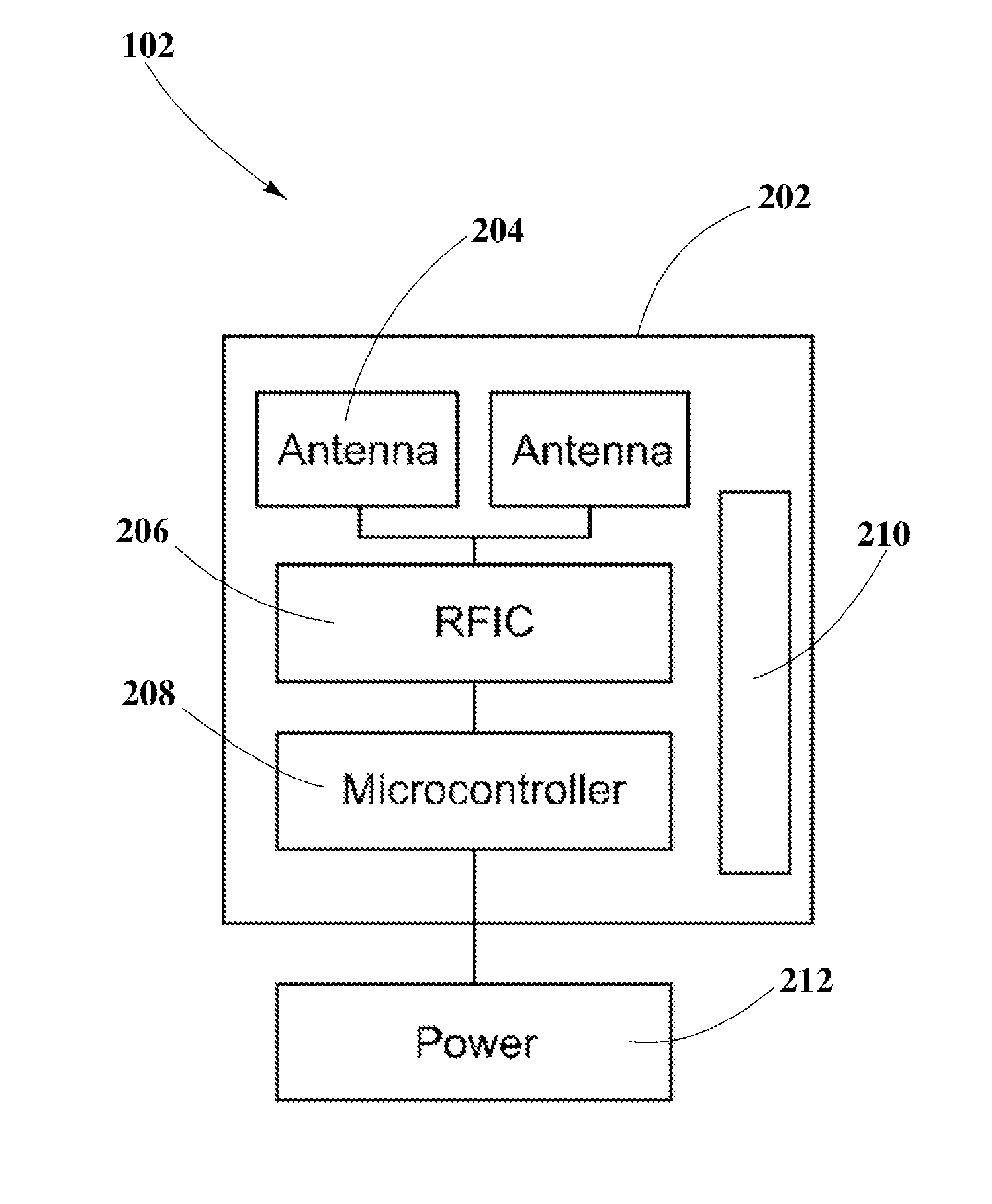
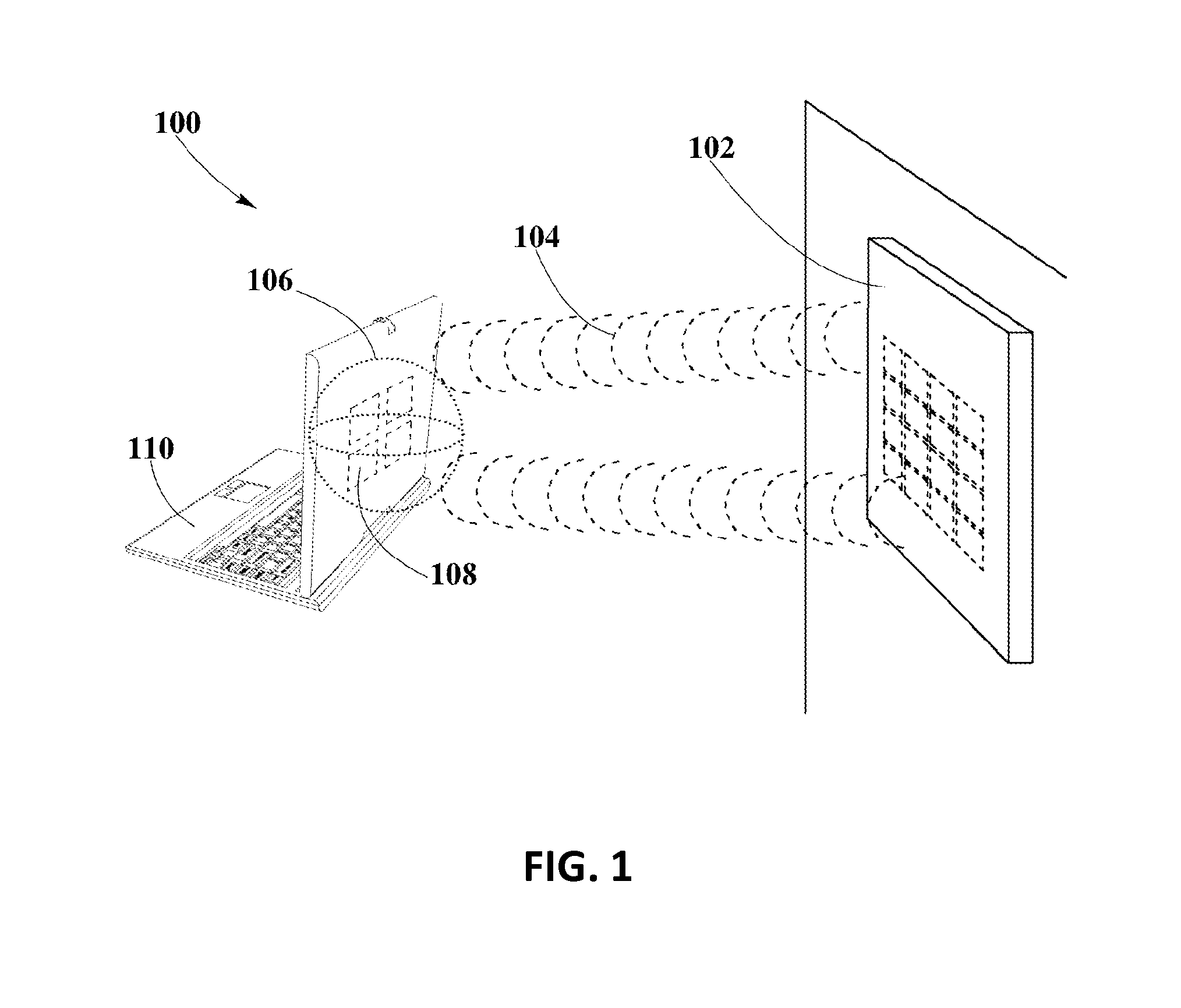
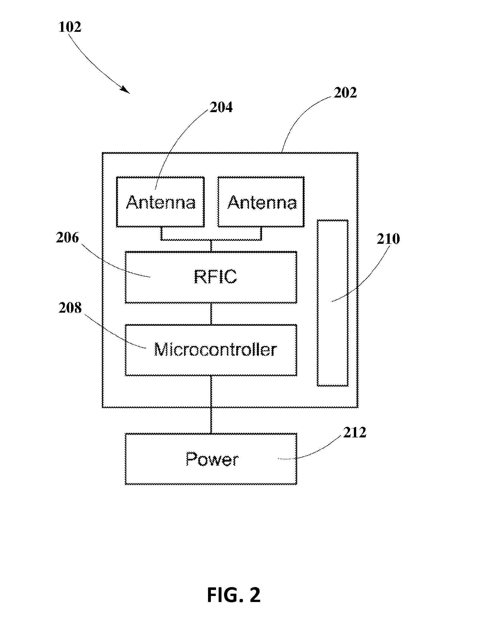
  • Methods and Systems for Maximum Power Point Transfer in Receivers
  • Methods and Systems for Maximum Power Point Transfer in Receivers
  • Methods and Systems for Maximum Power Point Transfer in Receivers

Examples


Embodiment Construction

[0018]The present disclosure is here described in detail with reference to embodiments illustrated in the drawings, which form a part here. Other embodiments may be used and / or other changes may be made without departing from the spirit or scope of the present disclosure. The illustrative embodiments described in the detailed description are not meant to be limiting of the subject matter presented here.

Definitions

[0019]As used here, the following terms may have the following definitions:

[0020]“Pocket-forming” refers to generating two or more RF waves that converge in 3-d space, forming controlled constructive and destructive interference patterns.

[0021]“Pockets of energy” refers to areas or regions of space where energy or power may accumulate in the form of constructive interference patterns of RF waves.

[0022]“Transmitter” refers to a device, including a chip which may generate two or more RF signals, at least one RF signal being phase shifted and gain adjusted with respect to othe...


PUM


Abstract

A MPPT management method in a receiver used for wireless power transmission may include the monitoring of the power extracted from RF waves at a dedicated antenna element in the receiver; detecting MPPT at an intelligent input boost converter in the receiver; comparing the detected MPPT with MPPT tables stored or calculated within a main system micro-controller in the receiver; adjusting the MPPT at the intelligent boost converter to find a suitable maximum peak that may enable an optimal power extraction from RF waves.

Description

CROSS-REFERENCE TO RELATED APPLICATIONS[0001]The present disclosure is related to U.S. non-provisional patent application DWV-3DPF-010 entitled “Methodology for Pocket-forming”; DWV-3DPF-015 entitled “Method for 3 Dimensional Pocket-forming”; DWV-3DPF-027 entitled “Receivers for Wireless Power Transmission”; DWV-3DPF-029 entitled “Transmitters for Wireless Power Transmission” invented by Michael Leabman, and ENG-SYHW-001 entitled “Enhanced Receiver for Wireless Power Transmission” invented by Jason Petras and Michael A. Leabman, each of which is incorporated by reference in its entirety hereinBACKGROUND[0002]1. Field of the Disclosure[0003]The present disclosure generally relates to wireless power transmission, and more specifically to a MPPT management method to effectively improve power extraction in receivers.[0004]2. Background Information[0005]Wireless power transmission may be based on the extraction and conversion of power or energy from transmitted RF waves. One challenge th...

Claims


Application Information

Patent Timeline
Patent Type & Authority Applications(United States)
IPC IPC(8): H02J17/00G05F5/00H02J7/02
CPCH02J17/00G05F5/00H02J7/025H02J7/00712H02J50/20H02J50/402H02J50/80H02J50/90H02J50/23H02J50/27H02J50/60H02J50/10
Inventor PETRAS, JASONLEABMAN, MICHAEL
Owner ENERGOUS CORPORATION
Learn More