High efficiency light source with integrated ballast

a ballast and high-efficiency technology, applied in the field of power supplies, can solve the problems of poor power factor, less efficient load of low-power factor, increased losses in power distribution systems, etc., and achieve the effect of improving driver efficiency and circuit efficiency

Inactive Publication Date: 2010-08-19
LIGHTING SCI GROUP
View PDF11 Cites 244 Cited by
  • Summary
  • Abstract
  • Description
  • Claims
  • Application Information

AI Technical Summary

Benefits of technology

[0019]8) An optional FET shunt used to improve circuit efficiency during periods of low current draw;
[0020]9) An optional high pass filter (HPF) used to slow the turn-on of the FETs during high peak currents, thereby improving the driver efficiency.

Problems solved by technology

Low-power-factor loads are less efficient and increase losses in a power distribution system.
Several problems exist with these conventional configurations.
This combination is required to supply continuous power to the switching circuit, but this results in a poor power factor since high peak current is drawn from the input in a small phase angle.
Second, the rectifier-capacitor front end (D2-D5 and C2) also delivers severely non-linear or intermittent performance when fed by industry standard solid state phase control dimming systems, wherein a silicon controlled switch such as a SCR or triac device is inserted in series with the ballast.
All of the dimming occurs during the small phase angle when current is drawn and the dimmer is rendered useless.
Third, system efficiency is adversely affected by the large number of components in the main power path.

Method used


Image

  • High efficiency light source with integrated ballast
  • High efficiency light source with integrated ballast
  • High efficiency light source with integrated ballast

Examples


Embodiment Construction

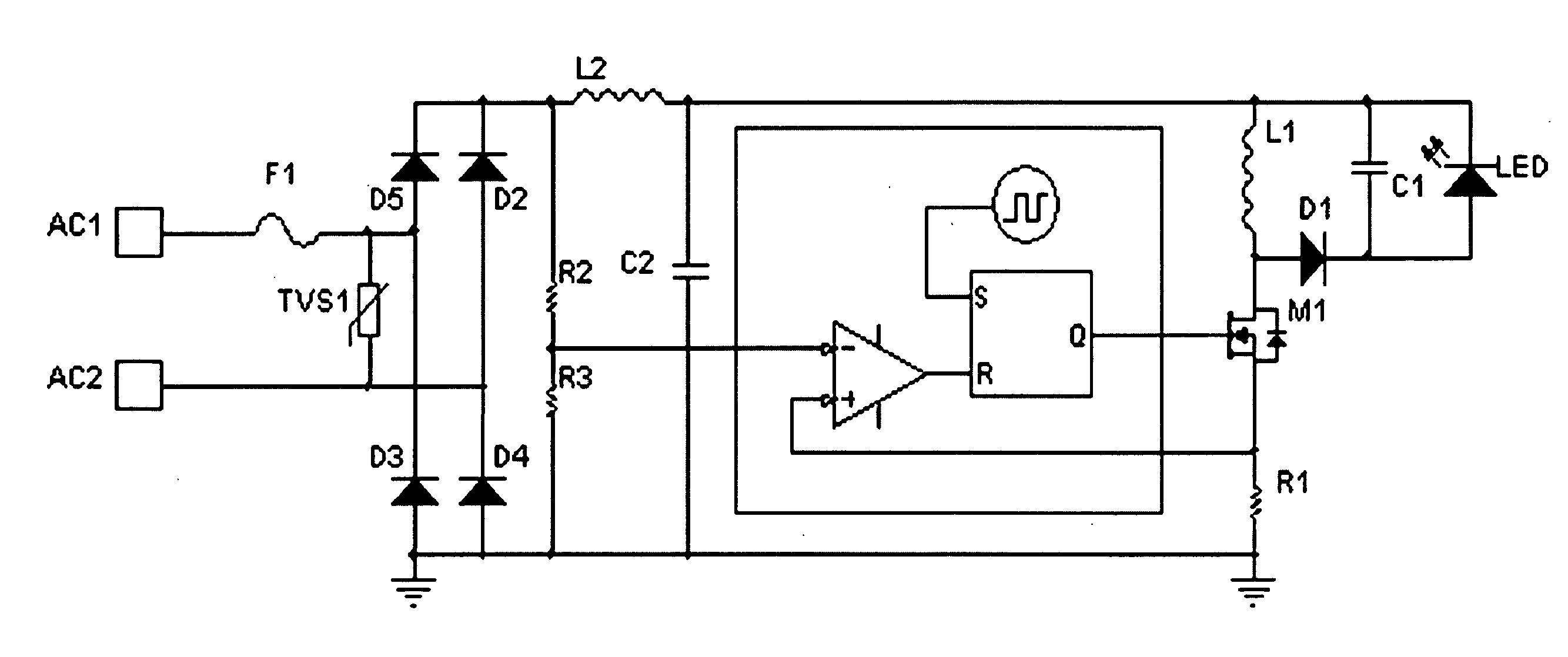
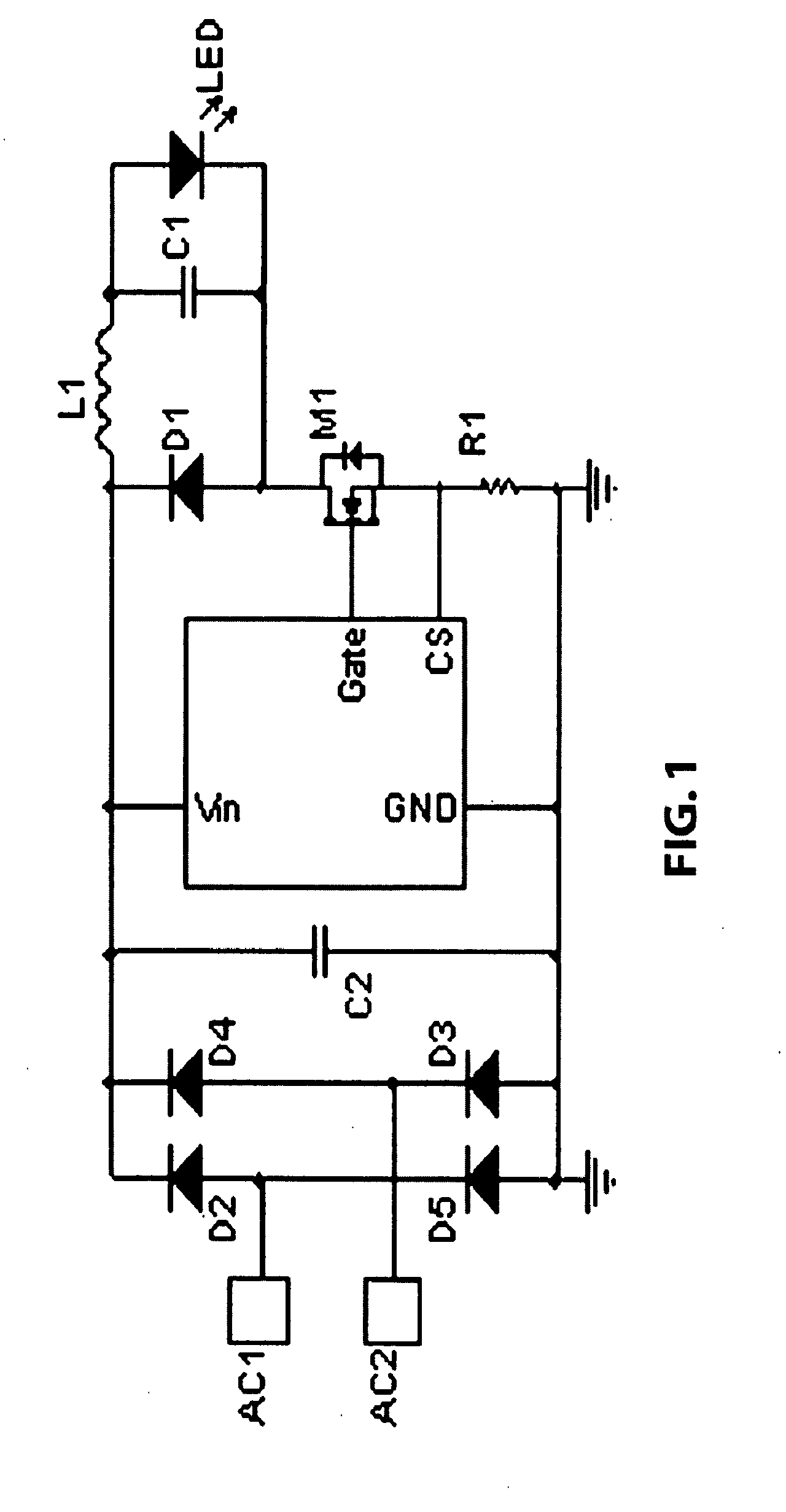
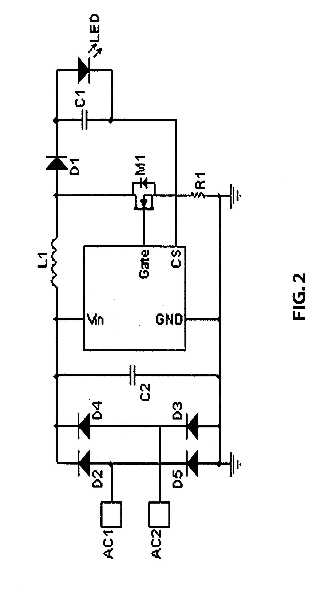
[0037]FIG. 4 is a schematic diagram showing an embodiment of the present invention. A buck-boost configuration is shown operating from an AC input voltage across input terminals AC1 and AC2, and driving an LED. For instance, with a 12 VAC input across AC1 and AC2, the LED may have a forward current of 400 mA and a forward voltage of 13 volts. A buck-boost topology is required since the rectified AC line voltage varies above and below the load voltage. The central portion of the circuit of FIG. 4 is enclosed in a box, wherein the box represents a switching power supply driver chip (“driver chip”), for instance the Supertex Inc. HV9910 or equivalent. The PWM generator of this driver chip may be represented functionally as an SR latch, oscillator, and comparator. The LED shown in all figures herein may also represent other kinds of loads, such as an array of LEDs or other type of solid state light source. A transient voltage suppressor (TVS) protects the circuit from voltage spikes on ...


PUM


Abstract

The present invention relates to regulated power supplies or ballasts integrated with an LED light source. The invention provides a power factor correction scheme producing a greater circuit power factor and improved frequency spectrum characteristics, in which a voltage corresponding to the instantaneous inductor current is sampled and compared to a scaled sample of the rectified input AC line voltage. The line voltage sample modulates the inductor peak charge current in the envelope of the rectified AC voltage waveform. This drives the LED output voltage at a frequency of twice the input line voltage frequency, such that no flicker is perceived in the light output because the persistence in LED phosphor assists in averaging the flux output.

Description

[0001]The present application claims the benefit of U.S. Provisional Application No. 60 / 983,043, filed on Oct. 26, 2007 which is hereby incorporated by reference in its entirety.[0002]Numerous references including various publications are cited and discussed in the description of this invention. The citation and / or discussion of such references is provided merely to clarify the description of the present invention and is not an admission that any such reference is “prior art” to the present invention. All references cited and discussed in this specification are incorporated herein by reference in their entirety and to the same extent as if each reference was individually incorporated by reference.FIELD OF THE INVENTION[0003]This invention relates to power supplies. More specifically, the present invention relates to regulated power supplies or ballasts integrated with a solid state light source such as Light Emitting Diodes (LEDs).BACKGROUND OF THE INVENTION[0004]Ballasts are most c...

Claims


Application Information

Patent Timeline
Patent Type & Authority Applications(United States)
IPC IPC(8): H05B37/02
CPCH05B33/0818H05B33/0815H05B45/3725
Inventor BURDALSKI, ROBERT J.SUNDELL, STEPHEN
Owner LIGHTING SCI GROUP
Why Eureka
Try Eureka