Cutout box fuse bypass jumper

Active Publication Date: 2016-01-26
BEERS RYAN +1
View PDF14 Cites 1 Cited by
  • Summary
  • Abstract
  • Description
  • Claims
  • Application Information

AI Technical Summary

Benefits of technology

[0006]The fuse bypass jumper of the present invention bridges the upper and lower fuse terminals of a high-voltage transmission line cut-out box so as to bypass the fuse element.

Problems solved by technology

This is a difficult and hazardous operation that requires at least two workers to connect both ends of the jumper across the cut-out box.
But these stretchable jumpers have two major drawbacks.
First, the operation of stretching the spring-tensioned jumper across the cut-out box is awkward and difficult to perform, especially

Method used


Image

  • Cutout box fuse bypass jumper
  • Cutout box fuse bypass jumper
  • Cutout box fuse bypass jumper

Examples


Embodiment Construction

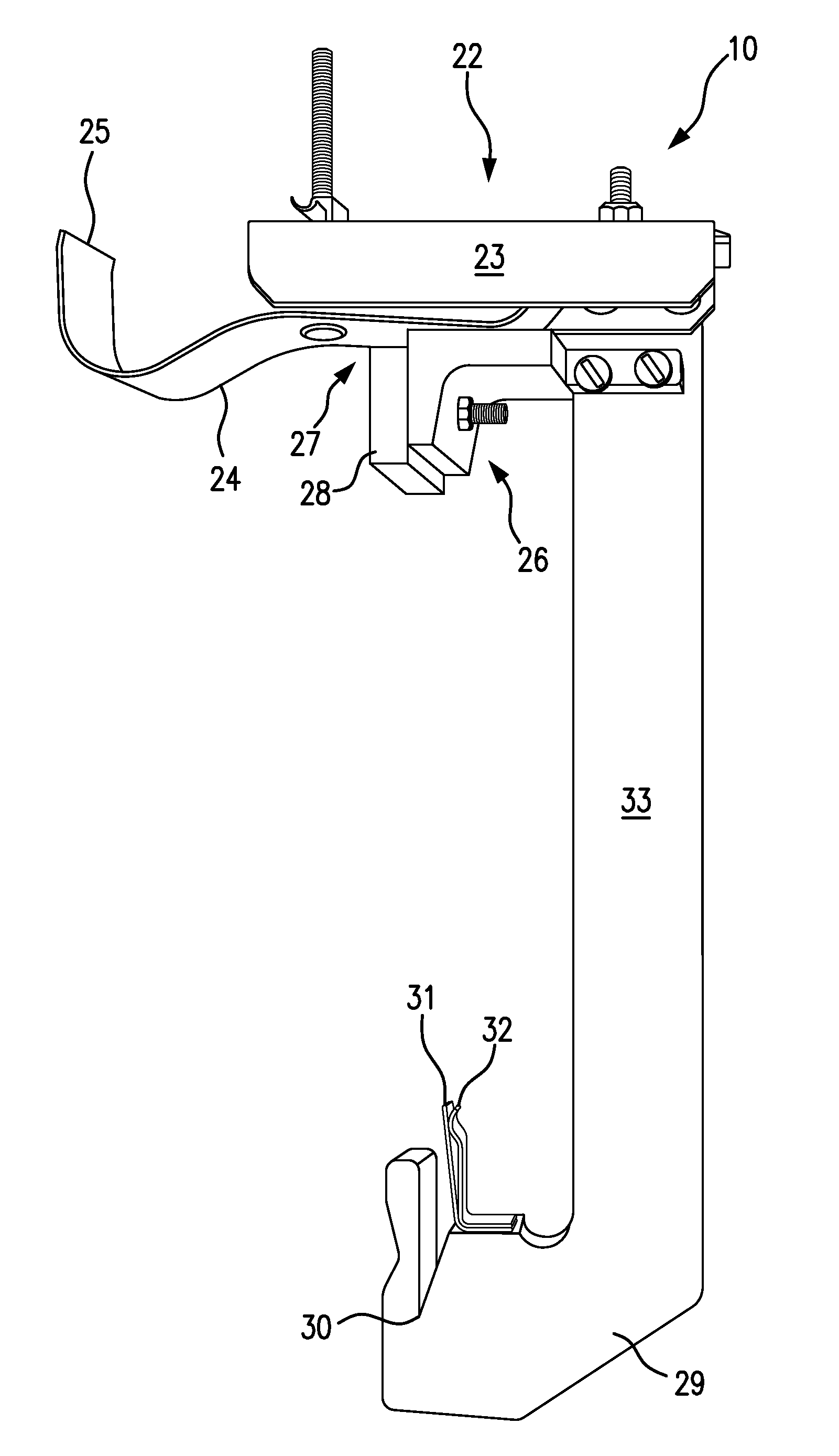
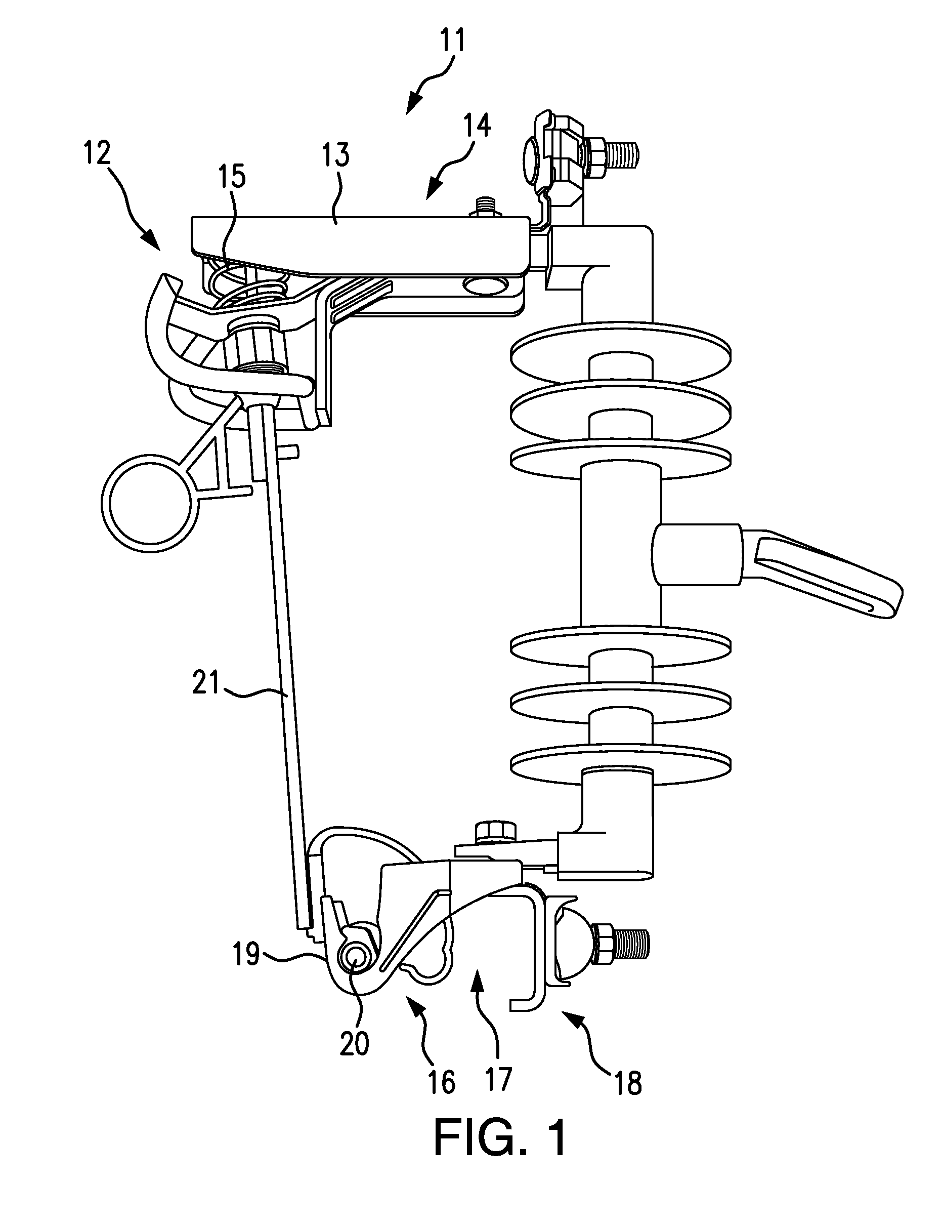
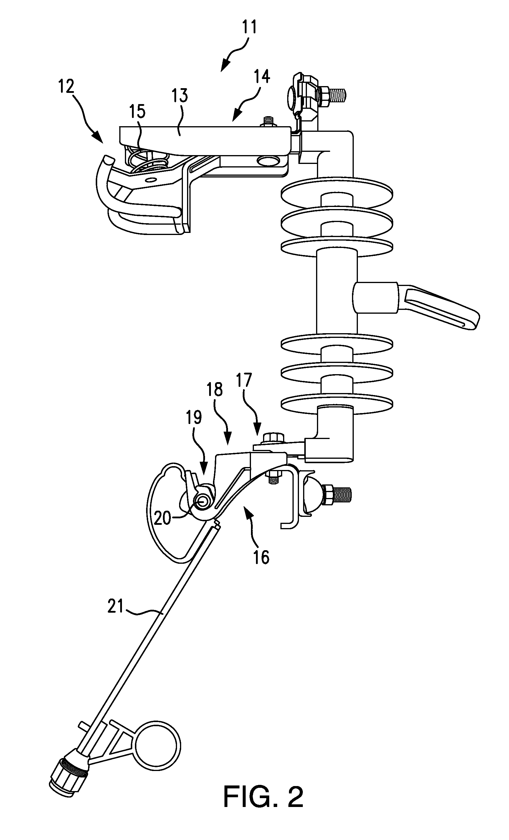
[0019]Referring to FIGS. 1 and 2, the fuse bypass jumper of the present invention 10 functions in conjunction with a cut-out box 11 in a high-voltage electrical transmission circuit. The cut-out box 11 has an upper fuse terminal 12 electrically connected to an upper terminal extension 13, which forms the upper lateral arm 14 of the cut-out box. The upper fuse terminal 12 is typically tensioned with a coil spring 15. The cut-out box 11 also has a lower fuse terminal 16 electrically connected to a lower terminal extension 17, which forms the lower lateral arm 18 of the cut-out box 11. The lower fuse terminal 16 typically includes a fuse cradle 19 which accepts an axial pin or rod 20 on the lower end of the fuse element 21, so that the fuse element 21 can be rotated upward to engage the upper fuse terminal 12 and complete the circuit through the cut-off box 11, as depicted in FIG. 1. The fuse element 21 can also be rotated downward to disengage from the upper fuse terminal 12 and inter...


PUM


Abstract

The fuse bypass jumper of the present invention bridges the upper and lower fuse terminals of a high-voltage transmission line cut-out box so as to bypass the fuse element. The jumper comprises lateral upper and lower arms connected by a longitudinal jumper bar. The jumper arms and bar are made of a heavy gauge conductor rated for at least 100 Amps. With the jumper in place, the fuse element can be opened, removed and/or replaced without interrupting the transmission line circuit through the cut-off box, since the jumper now provides a bypass around the fuse. Since the bypass conductive path constitutes a heavy gauge, high-amperage bar conductor, this jumper can carry a much larger current load than flexible wire-based jumpers.

Description

FIELD OF INVENTION[0001]The present invention relates to the field of devices used in connection with the repair and maintenance of high voltage, high amperage power line facilities. More particularly, the present invention relates to devices used to bypass active power line fuses in connection with the inspection and / or replacement of such fuses.BACKGROUND OF THE INVENTION[0002]In high-voltage, high-amperage electrical transmission lines, fuses are used for protection against current overloads. Such fuses are typically incorporated in devices known as “cut-out boxes.” A cut-out box is a substantially rectangular structure, one side of which comprises a replaceable fuse element. As depicted in FIGS. 1 and 2, the lower end of the fuse element is typically rotatably attached to the cut-out box, while the upper end engages a spring-loaded contact. As shown in FIG. 2, the fuse element can be opened by rotating it outward, using a ring or “eye” attached to the fuse, and then removed by l...

Claims


Application Information

Patent Timeline
IPC IPC(8): H01R11/01H01H85/02H01R11/22H01H61/01H01H31/12
CPCH01H85/0208H01R11/22H01H61/01H01H31/127H01H2085/0216H01H31/006
Inventor BEERS, RYANPATRISSI, GARY
Owner BEERS RYAN
Why Eureka
Try Eureka