Supercharge Your Innovation With Domain-Expert AI Agents!

Method for recognizing a manipulation of a sensor and/or sensor data of the sensor

a technology of sensor data and recognition method, which is applied in the direction of digital transmission, liquid/fluent solid measurement, instruments, etc., can solve the problems of inability to recognize and understand the tuning of the vehicle, inability to store the storage space of the sensor, and inability to meet the requirements of software and hardware. , to achieve the effect of reducing software and hardware requirements, simple and fast, and high security

Active Publication Date: 2016-02-02
ROBERT BOSCH GMBH
View PDF3 Cites 8 Cited by
  • Summary
  • Abstract
  • Description
  • Claims
  • Application Information

AI Technical Summary

Benefits of technology

[0006]The present invention is intended to provide a method for recognizing a manipulation of transmitted sensor data and / or a sensor itself, which meets similarly high security demands as the complex methods known from the related art, on the one hand, and is substantially simpler and faster and in particular involves significantly lesser software and hardware demands than the known methods, on the other hand.
[0007]An object which is to be achieved by the present invention is thus to provide a mechanism, which permits the ECU and later the vehicle manufacturer to detect and comprehend engine tuning. More precisely, any type of manipulation of the sensor data transmitted from the sensor to the ECU is to be detected. In addition, the provided manipulation recognition is to be provided at the lowest possible costs with respect to the chip surface area required for the implementation, the processing power of the processor, and the storage requirement, in particular with respect to a secure, nonvolatile memory.
[0024]In the ideal case, the secret key is only known to the sensor and the ECU. However, it is also conceivable that the secret key is stored, for example, at the manufacturer of the sensor, the vehicle manufacturer, or another authorized institution (a person, a company, or an authority) or may be regenerated thereby if needed in another way. This has the advantage that in the event of a replacement of the sensor, the matching secret key may be copied into a memory of the ECU, so that it is able to communicate properly with the new sensor, in particular a manipulation of the transmitted sensor data and / or the sensor may thus be recognized by the ECU. Only if both the sensor and the ECU have the same secret key may the sensor ascertain the correct session key, which is in turn a requirement for securing the subsequent transmission of the sensor data and the detection of a manipulation. Since the session key is generated in the sensor as a function of the secret key and is required to generate the message authentication code (MAC) for the sensor data which are to be transmitted or are transmitted from the sensor to the ECU, an authenticity of the sensor and an integrity of the transmitted data may only be verified as correct and proper in the control and / or regulating unit if both the sensor and the ECU have the same shared secret key.
[0027]To prevent an attack on the data transmission by replaying the same data (so-called replay attack), according to one particular specific embodiment, it is provided that the MAC is generated via both at least a part of the sensor data to be transmitted and via a counter value. The counter value is initialized at arbitrary points in time, which may be at the beginning of each session. In addition, the counter value is incremented or decremented at certain chronologically controlled or event-controlled points in time, which may be after every xth generation of a message authentication code (MAC), where xεN. In this way, it may be ensured that the data, on the basis of which the MAC is generated, differ from time to time, although the sensor data to be transmitted may be identical per se. A different authentication code (MAC) thus results from time to time even for identical sensor data. A replay attack may be effectively and efficiently prevented in this way.

Problems solved by technology

However, such tuning is not recognizable and not comprehensible for the vehicle manufacturer.
This has the disadvantage that the vehicle manufacturer in the past was made liable for any problems which resulted from the impermissible performance enhancement and had to repair defects of the internal combustion engine, although these were sometimes to be attributed to the impermissible performance enhancement.
Many of the methods may have the disadvantage that they are relatively costly and complex.
This requires additional storage space both in the sensor and in the ECU, storage space being scarce and costly in the sensor in particular.
In addition, the computer program for implementing the manipulation protection is relatively complex, and computing-intensive and storage-intensive as a result of the complexity of the method.

Method used


Image

  • Method for recognizing a manipulation of a sensor and/or sensor data of the sensor
  • Method for recognizing a manipulation of a sensor and/or sensor data of the sensor
  • Method for recognizing a manipulation of a sensor and/or sensor data of the sensor

Examples


Embodiment Construction

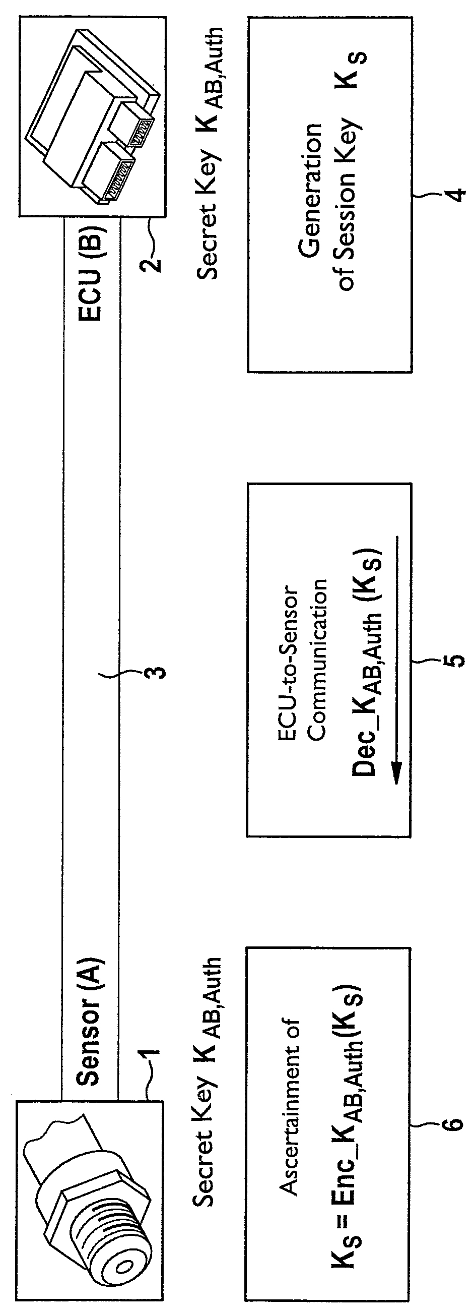
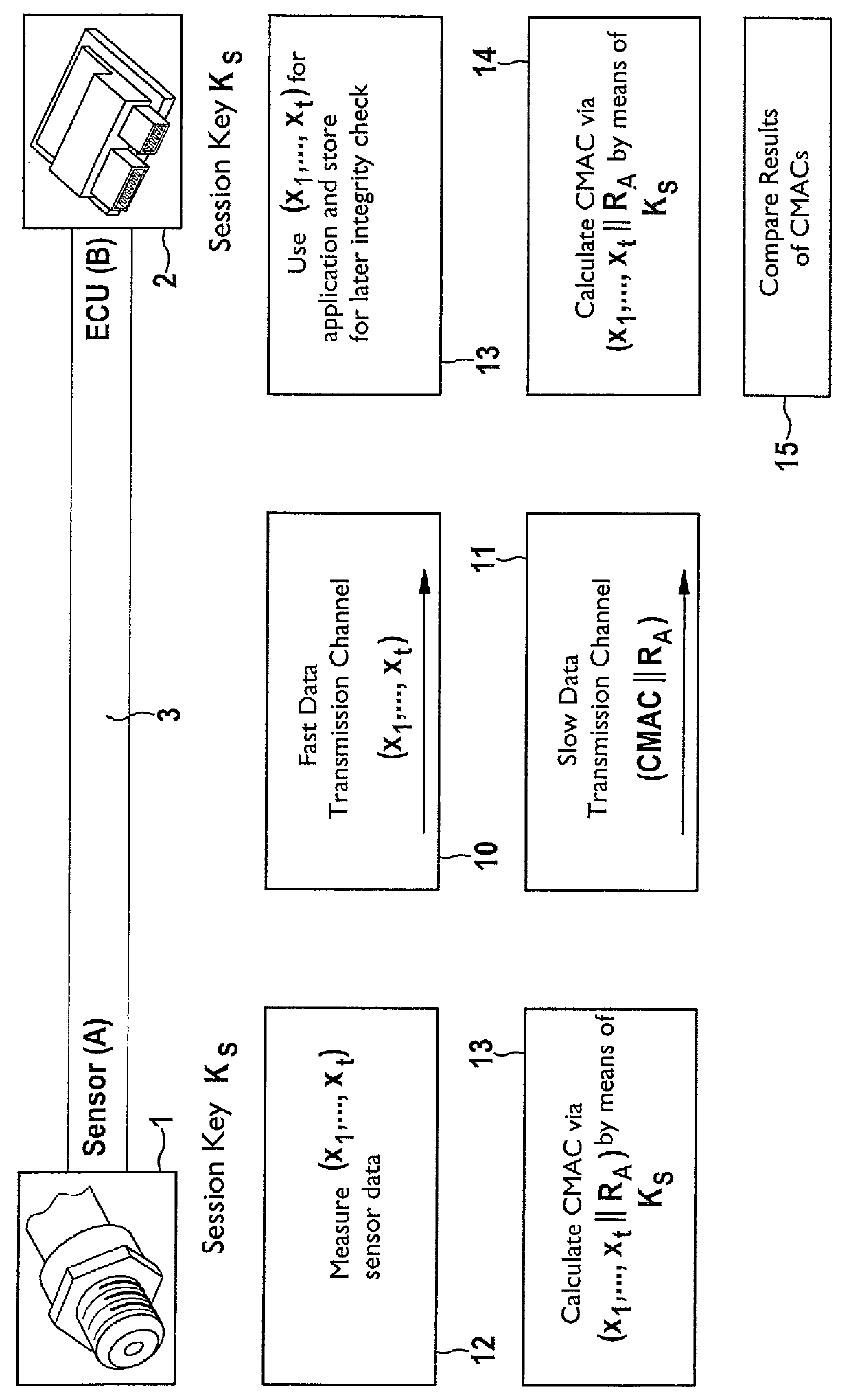
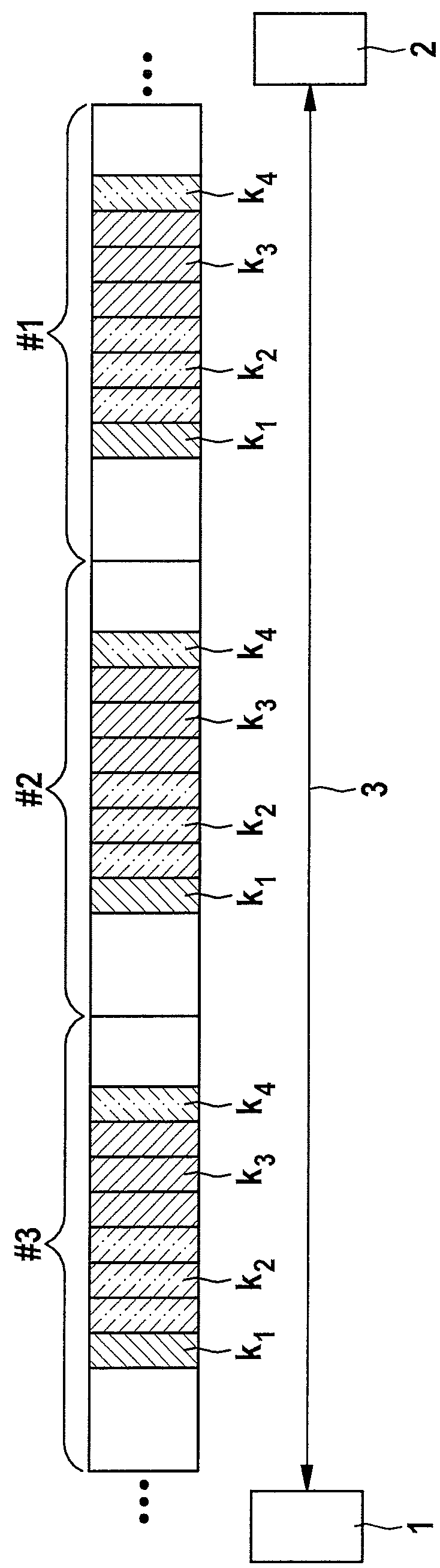
[0034]The present invention relates to a method for data transmission between a sensor and an electronic control and / or regulating unit (ECU). A manipulation of the transmitted sensor data and / or the sensor may be recognized. A sensor A is shown in the figures, which is identified with reference numeral 1. A control and / or regulating unit (ECU) B is identified with reference numeral 2. Sensor 1 may be connected via a physical data transmission channel in the form of a data transmission connection 3 to ECU 2. Data transmission connection 3 includes, for example, a two-wire line. Multiple data transmission channels are implemented on data transmission connection 3, via which data are transmitted between sensor 1 and ECU 2. Sensor 1 is configured, for example, as a pressure sensor for detecting the fuel pressure in a shared fuel accumulator (for example, common rail) of a fuel injection system of an internal combustion engine of a motor vehicle. Such a sensor 1 detects the fuel pressur...


PUM


Abstract

A method for data transmission between a sensor and an electronic control and / or regulating unit (ECU), the transmitted sensor data (x1, . . . , xt) and the sensor being secured against a manipulation. The system provides a particularly simple, but very secure method for manipulation protection, the sensor data (x1, . . . , xt) being transmitted via a first logical data transmission channel at a first data transmission rate, and security data (MAC; CMAC) for securing the transmitted sensor data and / or the sensor being transmitted via a second logical data transmission channel at a second data transmission rate from the sensor to the ECU. At least once at the beginning of a data transmission session, a session key is transmitted from the ECU to the sensor via a third logical data transmission channel and received by the latter, the session key being used at least for the ongoing session to generate the security data.

Description

RELATED APPLICATION INFORMATION[0001]The present application claims priority to and the benefit of German patent application no. 10 2013 206 185.4, which was filed in Germany on Apr. 9, 2013, the disclosure of which is incorporated herein by reference.FIELD OF THE INVENTION[0002]The present invention relates to a method for data transmission between a sensor and an electronic control and / or regulating unit, a manipulation of the transmitted sensor data and / or the sensor being recognized. The present invention additionally relates to a sensor, which is provided for connection to an electronic control and / or regulating unit and is configured to transmit sensor data to the control and / or regulating unit, an arrangement being provided for recognizing a manipulation of the transmitted sensor data and / or the sensor. Furthermore, the present invention relates to a control and / or regulating unit, which is provided for connection to a sensor and is configured to receive sensor data from the ...

Claims


Application Information

Patent Timeline
Patent Type & Authority Patents(United States)
IPC IPC(8): H04L9/00H04L9/32H04L9/08G08B21/00H04L9/06G06F1/26
CPCH04L9/0825H04L9/0822H04L9/3226H04L9/0637H04L2209/24H04L2209/84
Inventor LEWIS, MATTHEWIHLE, MARKUSSZERWINSKI, ROBERTSHOKROLLAHI, JAMSHIDGLAS, BENJAMIN
Owner ROBERT BOSCH GMBH
Features
  • R&D
  • Intellectual Property
  • Life Sciences
  • Materials
  • Tech Scout
  • Unparalleled Data Quality
  • Higher Quality Content
  • 60% Fewer Hallucinations
Learn More