
Method and device for detecting glare pixels of image

a technology of glare pixels and detection methods, applied in image enhancement, image analysis, instruments, etc., can solve the problems of unavoidable problems associated with light-related artifacts on images, unavoidable problems, and inability to detect glare pixels immediately

Active Publication Date: 2016-02-16
HTC CORP
View PDF8 Cites 9 Cited by
  • Summary
  • Abstract
  • Description
  • Claims
  • Application Information

AI Technical Summary

Problems solved by technology

However, the portability of such electronic devices may have prevented many more sophisticated uses or structures to be included for such cameras.
For example, fixed focal length lenses and small sensors would typically be used for such cameras since an optical zoom lens may be too heavy and require more physical depths than the body of the handheld electronic device would permit.
Presently, as such cameras are frequently used to take facial portraits in various events or gatherings, problems associated with light-related artifacts on the images could be unavoidable.
Such artifacts may not be immediately noticeable and the impacts on the quality of an image may not be appreciated after an image is taken.
A typical artifact encountered by the user may include glare.
One of the most common causes of glare is the light from a photographic flash.
Getting the best overall exposure from the combination of available light and flash illumination may pose a significant technical challenge, especially for the camera built-in to handheld electronic devices.
Unfortunately, this practice may be time intensive and cumbersome especially in the case of a large amount of images.
Also, the practice may produce unsatisfactory results if the users are not skillful in the use of image retouch or modification software.
On the other hand, although such algorithms have high detection rate on the artifact, they would highly depend on training data and model parameters as well as performance resource, power and time consuming arithmetic operations, which may be impractical for relatively inexpensive and memory-limited handheld electronic devices.

Method used


Image

  • Method and device for detecting glare pixels of image
  • Method and device for detecting glare pixels of image
  • Method and device for detecting glare pixels of image

Examples


Embodiment Construction

[0036]Reference will now be made in detail to the present embodiments of the invention, examples of which are illustrated in the accompanying drawings. Wherever possible, the same reference numbers are used in the drawings and the description to refer to the same or like parts.

[0037]No element, act, or instruction used in the description of the present application should be construed as absolutely critical or essential to the present disclosure unless explicitly described as such. Also, as used herein, each of the indefinite articles “a” and “an” is intended to exclude more than one item. If only one item is intended, the terms “a single” or similar languages could be used. Furthermore, the terms “any of” followed by a listing of a plurality of items and / or a plurality of categories of items, as used herein, are intended to include “any of”, “any combination of”, “any multiple of”, and / or “any combination of multiples of the items and / or the categories of items, individually or in c...


PUM


Abstract

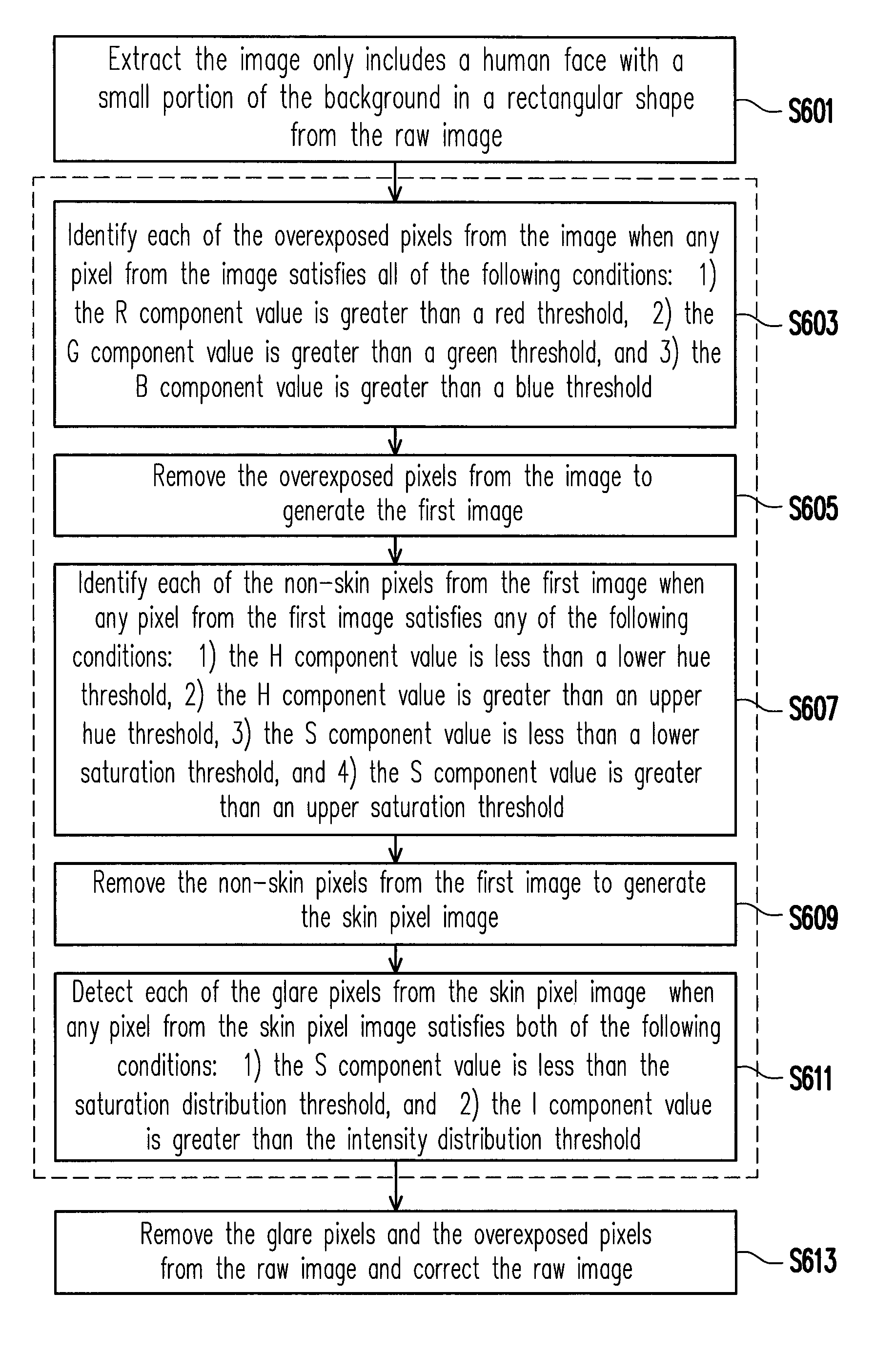
The present disclosure proposes a method and an electronic device for detecting glare pixels of an image including an object and an electronic device using the same. The method includes the following steps. First, the image is processed to remove overexposed pixels from the image to generate a first image. The first image is processed to remove non-object pixels from the first image to generate an object pixel image. The glare pixels are detected from the object pixel image according to a saturation distribution threshold and an intensity distribution threshold. The present disclosure is able to adjust the saturation distribution threshold and the intensity distribution threshold dynamically and adaptively to satisfy various kinds of objects and ambient lighting conditions so as to improve the probability of successful detection and reduce the probability of false alarms on the glare pixels.

Description

BACKGROUND OF THE INVENTION[0001]1. Field of the Invention[0002]The present disclosure generally relates to a method and a device for image processing. In particular, the present disclosure relates to a method and a device for detecting glare pixels of an image.[0003]2. Description of Related Art[0004]As a digital camera has become small, compact, and inexpensive, consequently, the digital camera could be embedded in handheld electronic devices such as cellular phones, smart phones, tablet computers, personal digital assistants (PDA) and so forth. The diminutive nature of such camera allows the camera to become a convenient and popular additional feature of portable consumer electronic devices. However, the portability of such electronic devices may have prevented many more sophisticated uses or structures to be included for such cameras. For example, fixed focal length lenses and small sensors would typically be used for such cameras since an optical zoom lens may be too heavy and ...

Claims


Application Information

Patent Timeline
Patent Type & Authority Patents(United States)
IPC IPC(8): G06K9/00G06K9/46G06T5/00G06T7/40
CPCG06K9/4652G06K9/46G06T5/005G06T7/408G06T2207/20076G06T2207/30201G06T7/90G06V40/10
Inventor CHIU, CHIA-WEI
Owner HTC CORP
Learn More