Intraocular camera for retinal prostheses

a retinal prosthesis and intraocular camera technology, applied in the field of prosthetic devices and methods, can solve the problems of increasing the difficulty of implantation of microstimulator arrays with photosensitive elements on planar substrates, catastrophic damage to the photoreceptor layer within the retina, and the inability to meet the needs of patients, etc., to achieve the effect of improving patient acceptability

Active Publication Date: 2012-06-12
UNIV OF SOUTHERN CALIFORNIA
View PDF40 Cites 70 Cited by
  • Summary
  • Abstract
  • Description
  • Claims
  • Application Information

AI Technical Summary

Benefits of technology

[0011]An intraocular camera for retinal prostheses may be used in place of an externally-mounted camera to provide capability for natural foveation, and may additionally provide an expanded depth of field that obviates the need for an additional accommodation mechanism. Furthermore, an advantage of the intraocular camera for retinal prostheses may be enhanced patient acceptability, as their appearance will be perceived as more typical of sighted individuals. In this context, exemplary embodiments of the intraocular “camera” may be described as intraocular video cameras, in that they may be capable of providing continuous (framed) video streams to the microstimulator array in real time or near real time. Provision for still image capture may be provided in such exemplary embodiments of intraocular cameras, in a manner that is either patient-controlled or physician-controlled, so that certain images within the patient's field of view may be studied in detail.
[0014]The set of optical elements may be antireflection coated (AR-coated) to eliminate spurious reflections and enhance image clarity in the presence of bright, localized light sources.

Problems solved by technology

Among the many causes of blindness, retinitis pigmentosa (RP) and age-related macular degeneration (AMD) are prevalent, causing catastrophic damage to the photoreceptor layer within the retina.
However, the implementation of such photosensitive elements within the microstimulator array has proven to be problematic for a number of reasons.
Hence, implantation of a microstimulator array with photosensitive elements incorporated on a planar substrate, such as is typical of most semiconductor devices and very large scale integrated (VLSI) circuits, becomes increasingly difficult as the size of the microstimulator array increases.
Second, the retinal tissue itself is fragile, and is easily damaged by the proximal implantation of devices with hard edges; again as is characteristic of most semiconductor devices and very large scale integrated (VLSI) circuits.
Fabricating a microstimulator array with incorporated photosensitive elements on a pliable or curved substrate is problematic because most semiconductor materials capable of supporting photosensitive elements, and of also supporting necessary circuitry for biasing and gain, and neither pliable nor curved.
Third, the incorporation of photosensitive elements without associated amplification is not capable of providing signals that are directly appropriate for localized electrical stimulation of the inner or outer layers of the retina.
Fourth, the incorporation of photosensitive elements within the microstimulator array itself requires a tradeoff of space (area on the supporting substrate) between the photosensitive elements and any associated circuitry, on the one hand, and the stimulation electrodes and any associated circuitry and electrical connections (interconnection wiring, or metal traces) on the other hand.
As microstimulator arrays are scaled up to higher and higher densities, the available space is increasingly required for the stimulation electrodes and interconnection wiring, leaving little if any space for localized photosensitive elements.
Sixth, the provision of electrical power for signal amplification at the surface of the retina is challenging, requiring an additional wired or wireless interconnection to the microstimulator array from the power source.
Finally, the incorporation of photosensitive elements within the microstimulator array makes the implementation of post-image-acquisition but pre-stimulation image processing functions problematic, as either additional power consumptive circuitry must be added to the microstimulator array to perform these functions, or a wired or wireless interconnection must be provided to an ancillary device within which such processing is performed.
Additionally, the use of an external camera for capturing images of the external world would require implanted patients to employ (at times rapid) head motion to search the visual field or track moving objects, which can in turn lead to disorientation, dizziness, and nausea.
Furthermore, the natural tendency of patients to foveate to the most visually interesting or important part of a scene would be to no avail with an externally-mounted camera coupled to the (internal) microstimulator array.
Such miniature cameras are not amenable to implantation within the human eye, as they are not designed specifically to work in conjunction with the biological corneal lens to comprise a two lens system that can form appropriate images of the external world on an image sensor array.
In addition, they are too large to fit within the confines of the human eye, much less the confines of a supportive membrane such as the crystalline lens sac.
The size of such cameras has been limited in large part by the difficulty of designing very short focal length lenses in the range of 1 to 3 mm with acceptable optical imaging performance.
Miniature cameras developed to date have too high a mass to be supported within the human eye in general, and within the crystalline lens sac in particular, especially considering the needs for chronic implantation and rapid foveation.
Such miniature cameras are also too power consumptive, which would lead to unacceptable temperature rises within the biological space surrounding an implanted intraocular camera.

Method used


Image

  • Intraocular camera for retinal prostheses
  • Intraocular camera for retinal prostheses
  • Intraocular camera for retinal prostheses

Examples


Embodiment Construction

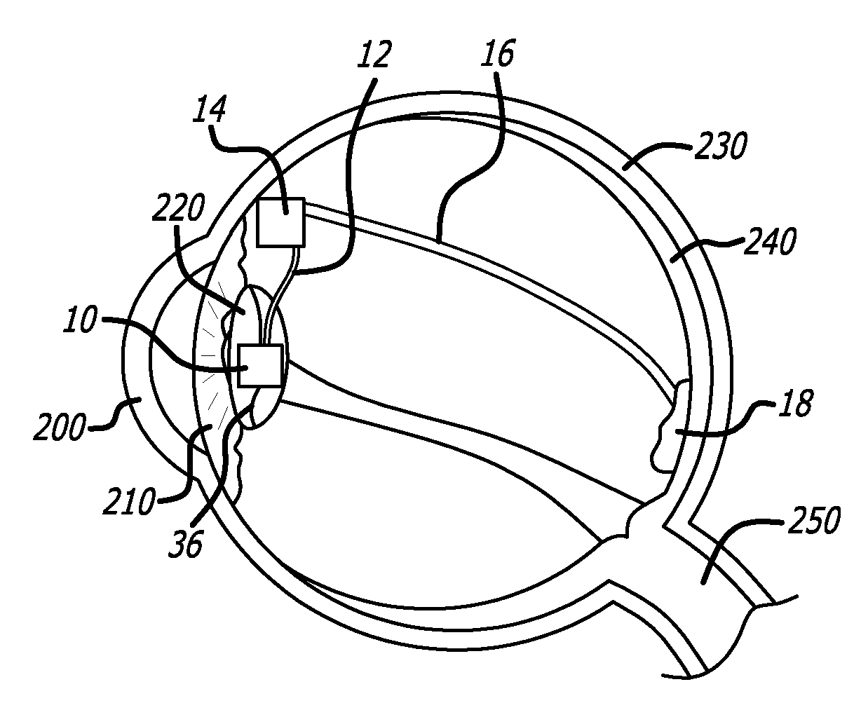
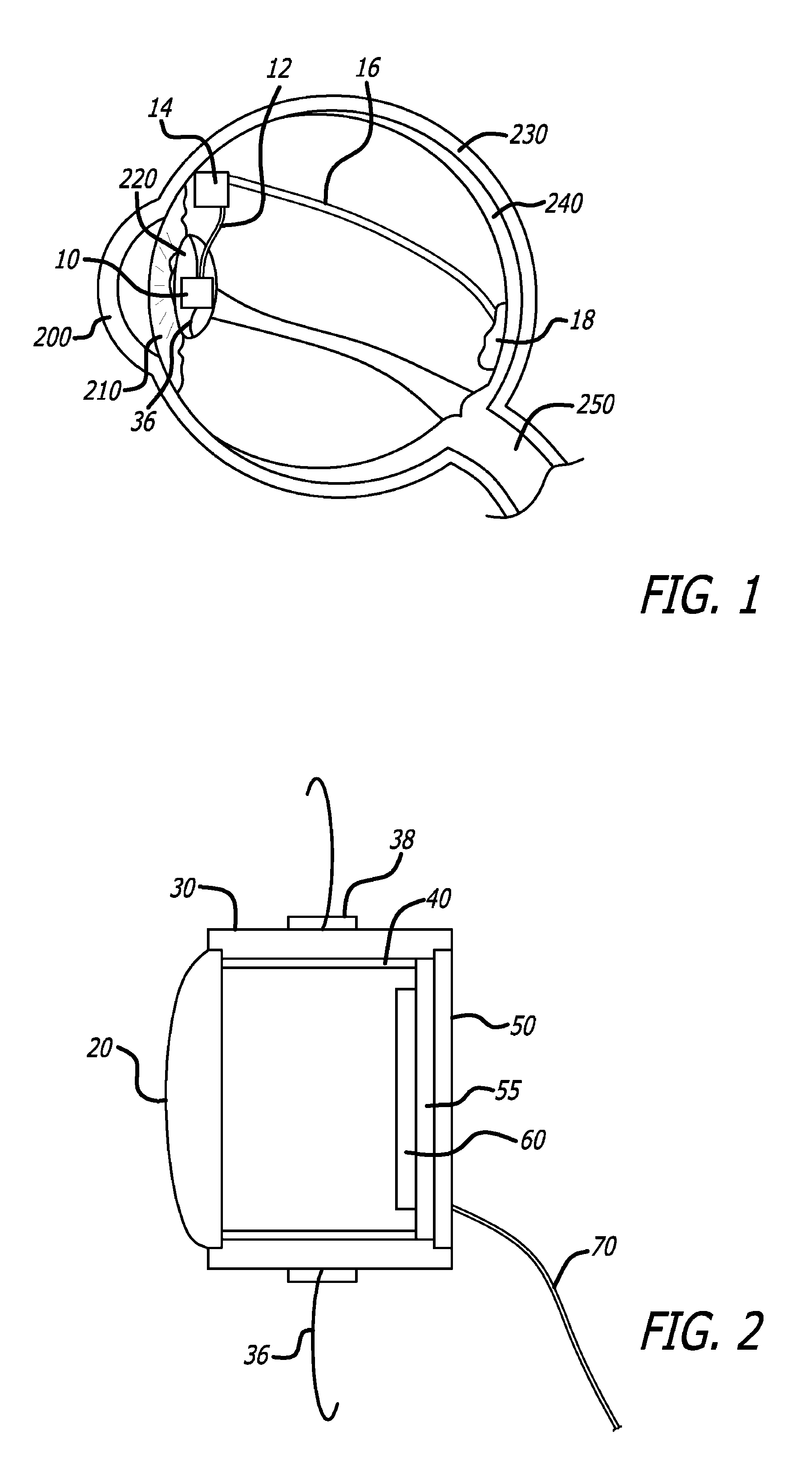
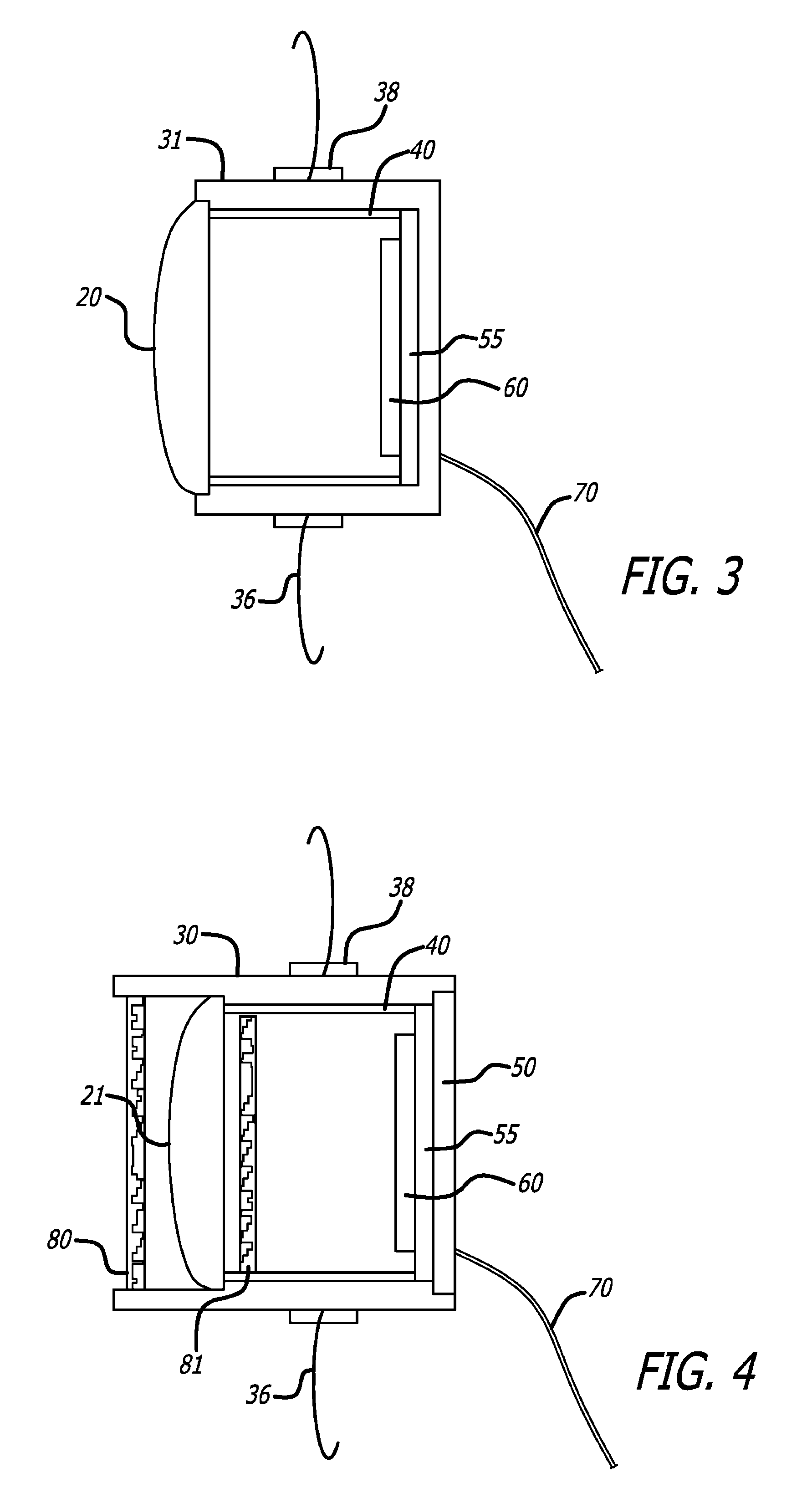
[0032]The detailed description set forth below is intended as a description of exemplary embodiments of intraocular cameras for retinal prostheses and is not intended to represent the only embodiments in which such intraocular cameras and related image gathering methods can be practiced. The term “exemplary” used throughout this description means “serving as an example, instance, or illustration,” and should not necessarily be construed as preferred or advantageous over other embodiments. The detailed description includes specific details for the purpose of providing a thorough understanding of the principles of operation and various embodiments of intraocular cameras for retinal prostheses. However, it will be apparent to those skilled in the art that the development and implementation of intraocular cameras for retinal prostheses may be practiced without these specific details. In some instances, well-known structures and devices are shown in block diagram form in order to avoid o...


PUM


Abstract

An intraocular camera for retinal prostheses may include an optical imaging system comprising a set of optical elements for forming an image of the external world on an image sensor array, wherein the optical elements and the image sensor array may be enclosed in an implantable biocompatible housing that may employ haptic elements for stabilization within the eye. The set of optical elements may be designed to have a short focal length and to provide adequate resolution images that can be transformed into a set of stimulation signals applied to a pixellated microstimulator array. Transmission of the signals from the intraocular camera to a microstimulator driver circuit may be accomplished either by a wired or wireless communication device. Power and control signals may be provided to the intraocular camera by a wired or wireless communication device, or optically by means of ambient illumination or an optical beam.

Description

CROSS-REFERENCE TO RELATED APPLICATIONS[0001]This application claims priority to U.S. Provisional Application Ser. No. 60 / 746,588 filed on May 5, 2006, entitled “Intraocular Camera for Retinal Prosthesis,” the entire content of which is incorporated herein by reference.STATEMENT REGARDING FEDERALLY SPONSORED RESEARCH[0002]This invention was made with government support under Grant No. NSF EEC-0310723, awarded by the National Science Foundation. The government has certain rights in the invention.BACKGROUND[0003]1. Field[0004]This application relates generally to prosthetic devices and methods for restoring sight to the blind.[0005]2. Description of Related Art[0006]Among the many causes of blindness, retinitis pigmentosa (RP) and age-related macular degeneration (AMD) are prevalent, causing catastrophic damage to the photoreceptor layer within the retina. Recent studies have demonstrated, however, that the inner layers of the retina remain for the most part intact even many years aft...

Claims


Application Information

Patent Timeline
Patent Type & Authority Patents(United States)
IPC IPC(8): A61F2/16
CPCA61F9/08A61N1/36046A61N1/0543
Inventor NASIATKA, PATRICK J.HAUER, MICHELLE C.STILES, NOELLE R. B.TANGUAY, JR., ARMAND R.HUMAYUN, MARK S.
Owner UNIV OF SOUTHERN CALIFORNIA
Why Eureka
Try Eureka