Method and apparatus for optimizing germicidal lamp performance in a disinfection device

a disinfection device and germicidal lamp technology, applied in electrical equipment, cooling/ventilation/heating modification, radiation, etc., can solve the problems of high risk of overheating and even melting of malgam spots

Active Publication Date: 2016-02-16
ULTRAVIOLET DEVICES
View PDF30 Cites 13 Cited by
  • Summary
  • Abstract
  • Description
  • Claims
  • Application Information

AI Technical Summary

Benefits of technology

[0014]It is highly desirable to be able to utilize germicidal lamps and in particular very high output germicidal lamps for air and surface applications. The present invention discusses a novel approach to utilize the very high UVC output of germicidal amalgam lamps in UVC disinfection devices in air and surface applications by providing a means to reduce and / or control the temperature of the amalgam spot(s) thus allowing the lamp to operate in its ideal operating range.
[0015]Another object of this invention is to allow the use of the germicidal amalgam lamp for use in a vertical configuration in a UVC disinfection device by ensuring that the amalgam is kept in its position and operating within the ideal temperature range. Yet another object of this invention is to reduce or eliminate the possibility of the amalgam melting. The present invention allows the germicidal amalgam lamps to be used in devices for air and surface disinfection where the amalgam lamp is exposed to ambient air. The invention discloses a novel approach to cool and / or control the temperature of the amalgam spot, thereby preventing the amalgam spot from melting and allowing the lamp to operate in an ideal operating temperature range and deliver maximum UVC output.
[0016]An example of a UVC disinfection device is the V-360+ mobile disinfection device, by UltraViolet Devices, Inc., which is used to disinfect surfaces in a healthcare environment. It is therefore highly desirable to utilize amalgam lamps to maximize the UVC output of the V360+ device and allow rapid disinfection times. The V-360+ device (See FIG. 1) utilizes more than one or four germicidal amalgam lamps which are located around a highly reflective hollow cylindrical aluminum support / conduit mounted at the center of a circular base. The combination of the high output amalgam lamps and the highly reflective support allows the V360+ device to deliver a high dose of UVC in order to achieve high levels of disinfections and rapid disinfection times.

Problems solved by technology

However, with the lamps positioned in a vertical configuration, the amalgam spots are highly susceptible to overheating and even melting and moving out of position due to conditions described previously.

Method used


Image

  • Method and apparatus for optimizing germicidal lamp performance in a disinfection device
  • Method and apparatus for optimizing germicidal lamp performance in a disinfection device
  • Method and apparatus for optimizing germicidal lamp performance in a disinfection device

Examples


Embodiment Construction

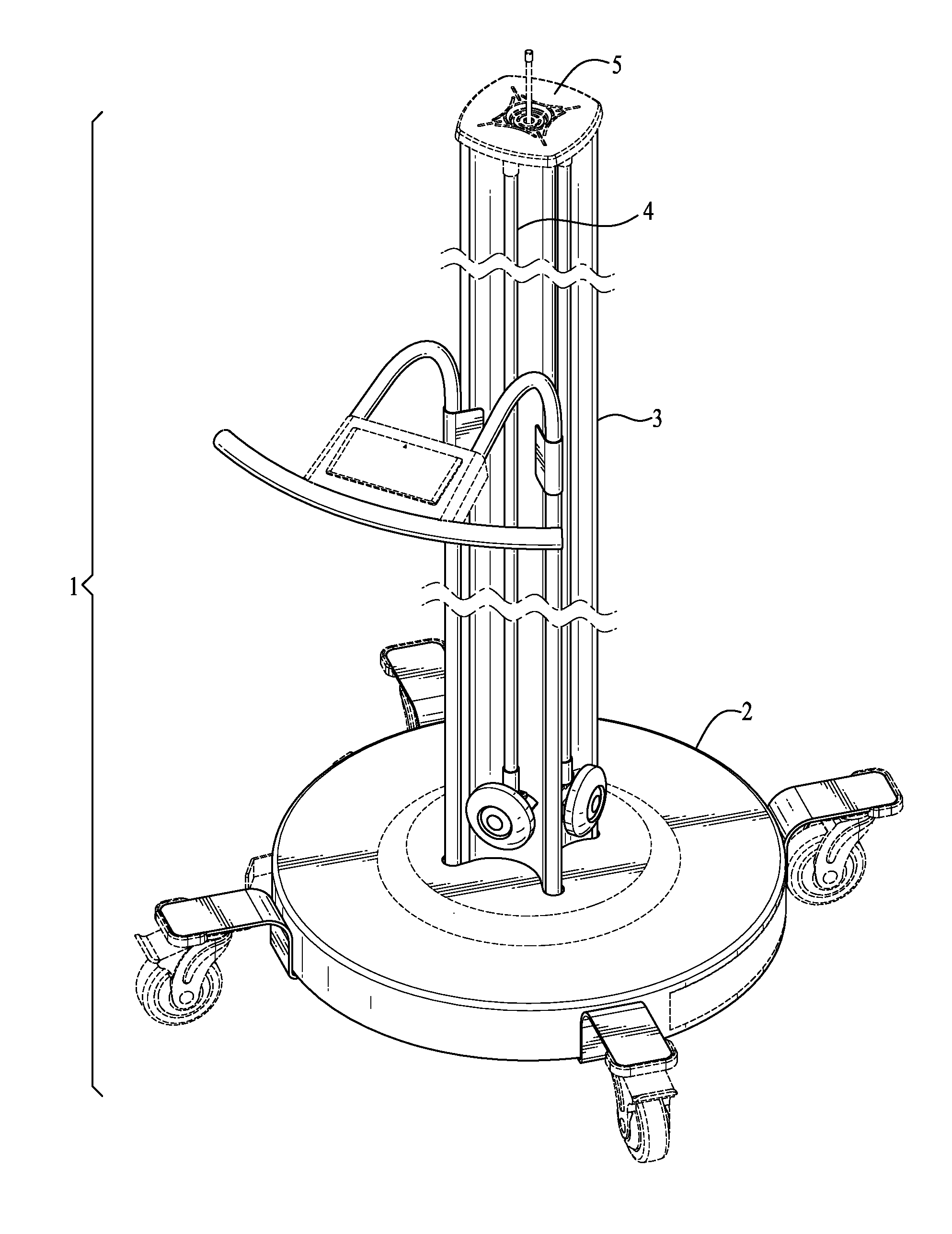
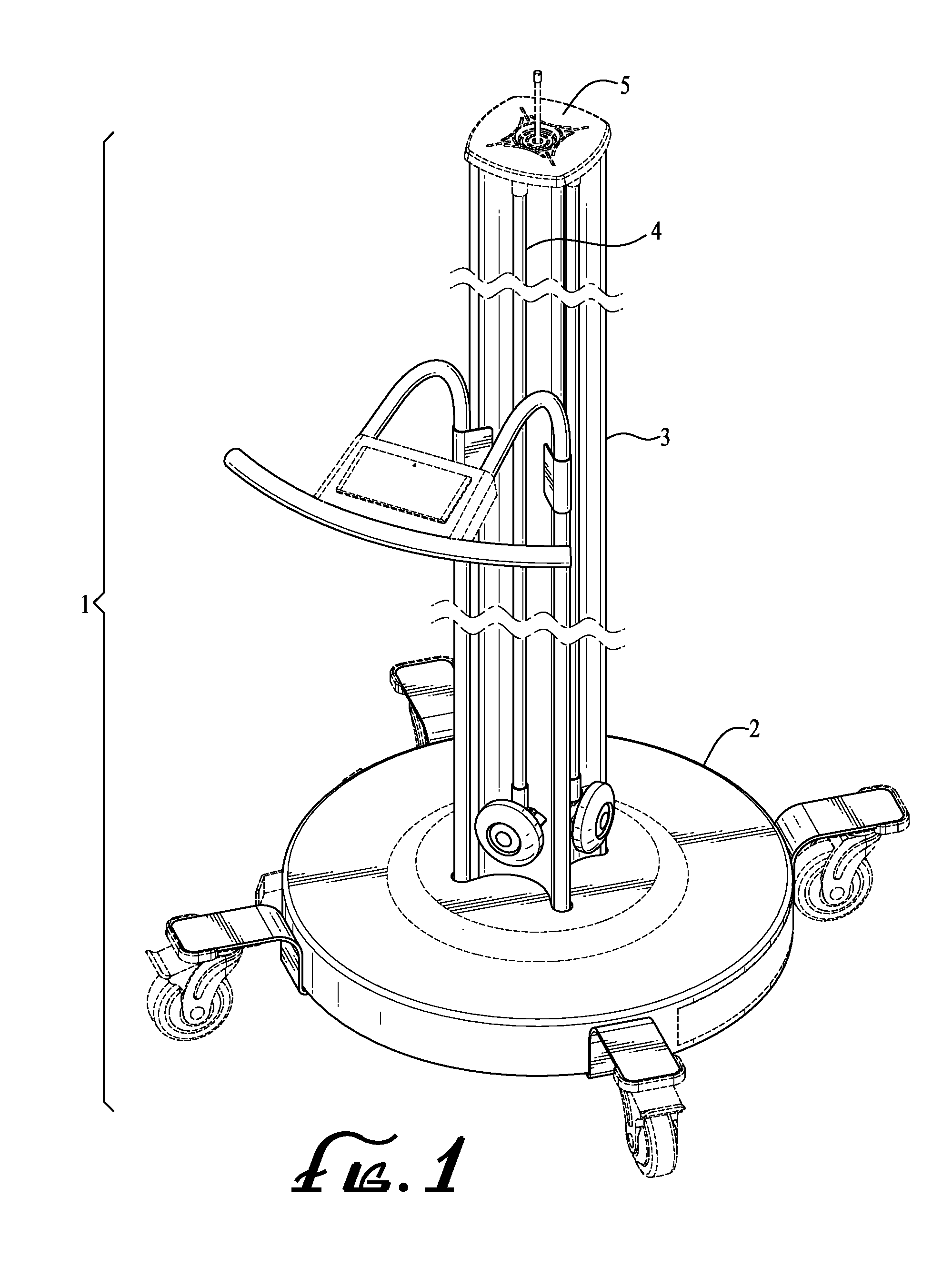
[0036]Referring to FIG. 1, a typical device 1 for the UV disinfection of air or surfaces is shown. The basic elements of the device are a base 2, a support, in this case, acting also as a conduit 3 and an opening 5 for the exit of air. One or more lamps 4 are installed around the support or conduit 3.

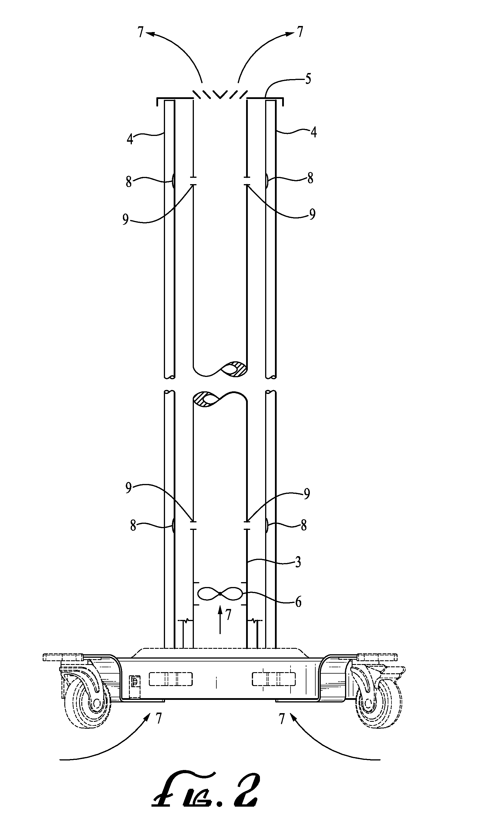
[0037]FIG. 2 shows the typical device 1, in cross section. An air moving device 6, including without limitation a fan or blower, is installed in the conduit 6 or may be installed in the base 2. The air moving device 6 causes air 7 to move into the conduit 3 and much of the air to exit through opening 5. Orifices, openings or holes 9 of a specific pre-determined diameter are placed in the conduit 4 at a strategic point selected to direct the air 7 through the orifices 9 to an area near or at the critical spot or points 8 (including mercury spot or amalgam spot, which contains mercury) on the lamp 4.

[0038]In another embodiment, not shown, the opening 5 may be omitted allowing all the air ...


PUM

PropertyMeasurementUnit
spectral wavelengthaaaaaaaaaa
UVC wavelengthaaaaaaaaaa
temperatureaaaaaaaaaa

Abstract

This invention controls the temperature of the critical spot of the UV lamps and on the critical spots having a deposit of mercury or amalgam containing mercury by directing a uniform flow of air on and around the critical spots having amalgam or be other means to remove heat from the critical spots.

Description

PRIORITY CLAIM[0001]This application claims the benefit of U.S. Provisional Patent Application No. 61 / 895,010, filed on Oct. 24, 2013, which is incorporated by reference in entirety. This application is also related to U.S. Design Pat. No. D684,671, which was issued on Jun. 19, 2013, which is also incorporated by reference in entirety.BACKGROUND OF THE INVENTION[0002]The effectiveness of germicidal ultraviolet (UV-C) irradiation as a powerful disinfecting technology has been well documented in peer-reviewed literature as well as in practice. Germicidal UV-C disinfection has been used for decades in disinfecting municipal drinking water, waste water, and in air and surface applications to disinfect against various micro-organisms such as bacteria, virus and mold. UVC devices employ one or more lamps emitting a spectral wavelength output of approximately 254 nm which disrupts the DNA structure of the micro-organisms, rendering them harmless and unable to reproduce.[0003]The lamps typi...

Claims


Application Information

Patent Timeline
Patent Type & Authority Patents(United States)
IPC IPC(8): A61L2/10A61L9/20H05K7/20
CPCH05K7/20136A61L2/10A61L9/20H05K7/20436
Inventor SHOSTAK, ALEKSANDRMATHUR, ASHISHHAYES, RICHARDVELOZ, PETERWITHAM, DAVIDBETANCOURT, FILIBERTOROTKOP, LEV
Owner ULTRAVIOLET DEVICES
Why Eureka
Try Eureka