
Pumpless fluid dispenser

a dispenser and fluid technology, applied in the field of dispensers, can solve the problems of high cost of purchase and maintenance, inability to operate efficiently under low pressure, and many engines, and achieve the effect of facilitating energy transfer

Active Publication Date: 2016-02-23
CRYOGENIC IND LLC
View PDF39 Cites 20 Cited by
  • Summary
  • Abstract
  • Description
  • Claims
  • Application Information

AI Technical Summary

Benefits of technology

The present patent provides a pumpless fluid dispensing system that includes two tanks and conduits for transferring fluid between them. The system includes a conditioning system with a heat exchanger and a control system for measuring and controlling the properties of the fluid. The system can be used to dispense liquefied natural gas (LNG) without the need for a pump. The technical effects of the invention include improved efficiency, reduced energy consumption, and reduced noise levels during fluid dispensing.

Problems solved by technology

This presents a range of issues, including station maintenance, safety, and accuracy.
Further, LNG dispensers should be able to do this with minimized venting of LNG to the atmosphere, because venting wastes LNG and poses potential environmental and safety concerns.
While storing bulk quantities of LNG at low pressures is more convenient, many engines cannot operate efficiently under low pressures.
Such equipment, however, may be expensive to purchase and maintain, adding to maintenance and operation costs of dispensing stations.
Accordingly, such devices add to the size, weight, and complexity of dispensing systems.

Method used


Image

  • Pumpless fluid dispenser
  • Pumpless fluid dispenser
  • Pumpless fluid dispenser

Examples


Embodiment Construction

[0017]Reference will now be made in detail to the exemplary embodiments of the present disclosure described below and illustrated in the accompanying drawings. For convenience, the term “proximal” will be used herein to mean closer to the bulk storage tank described herein, and the term “distal” will be used herein to mean closer to the use device, described herein as a vehicle.

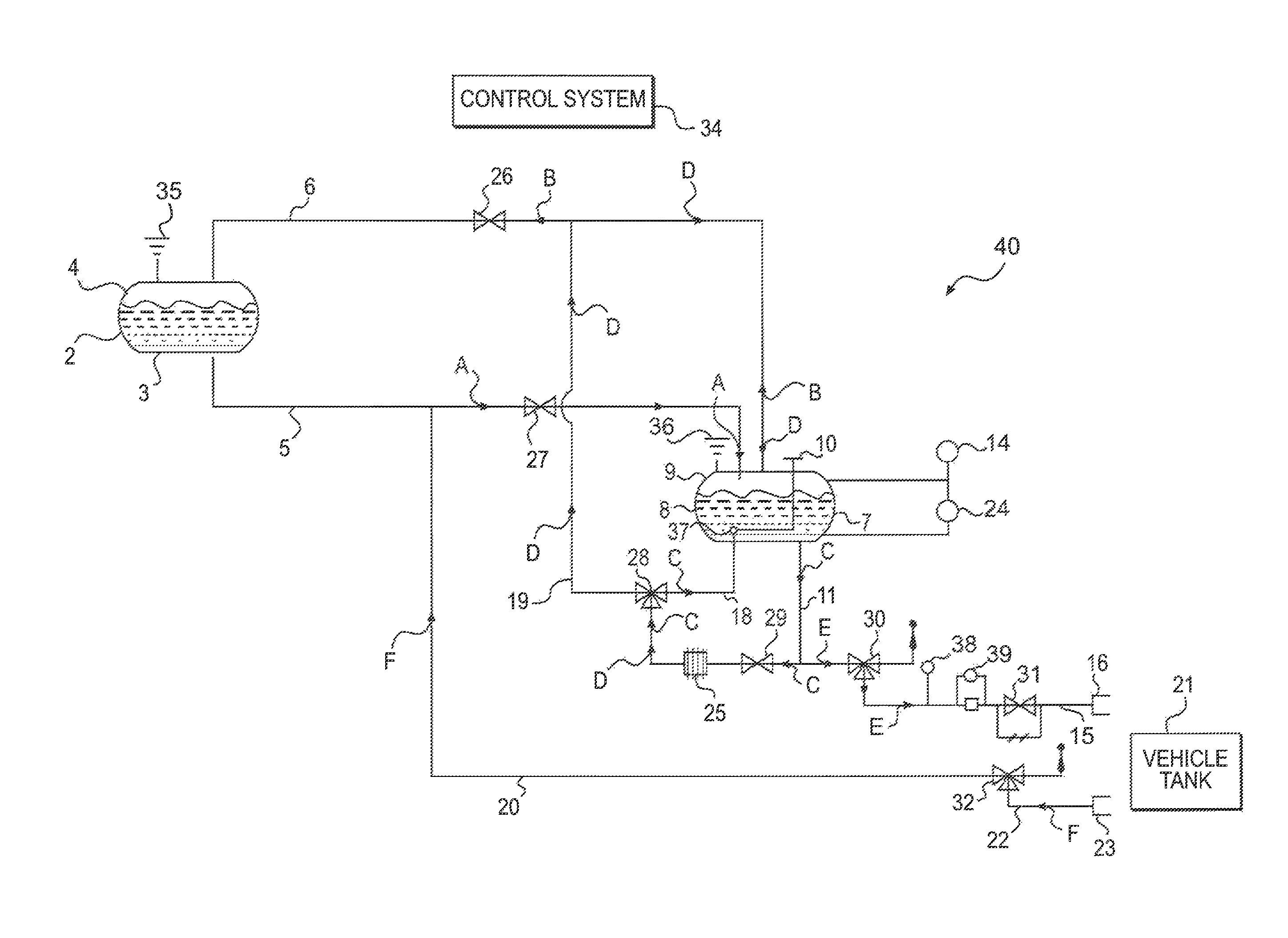
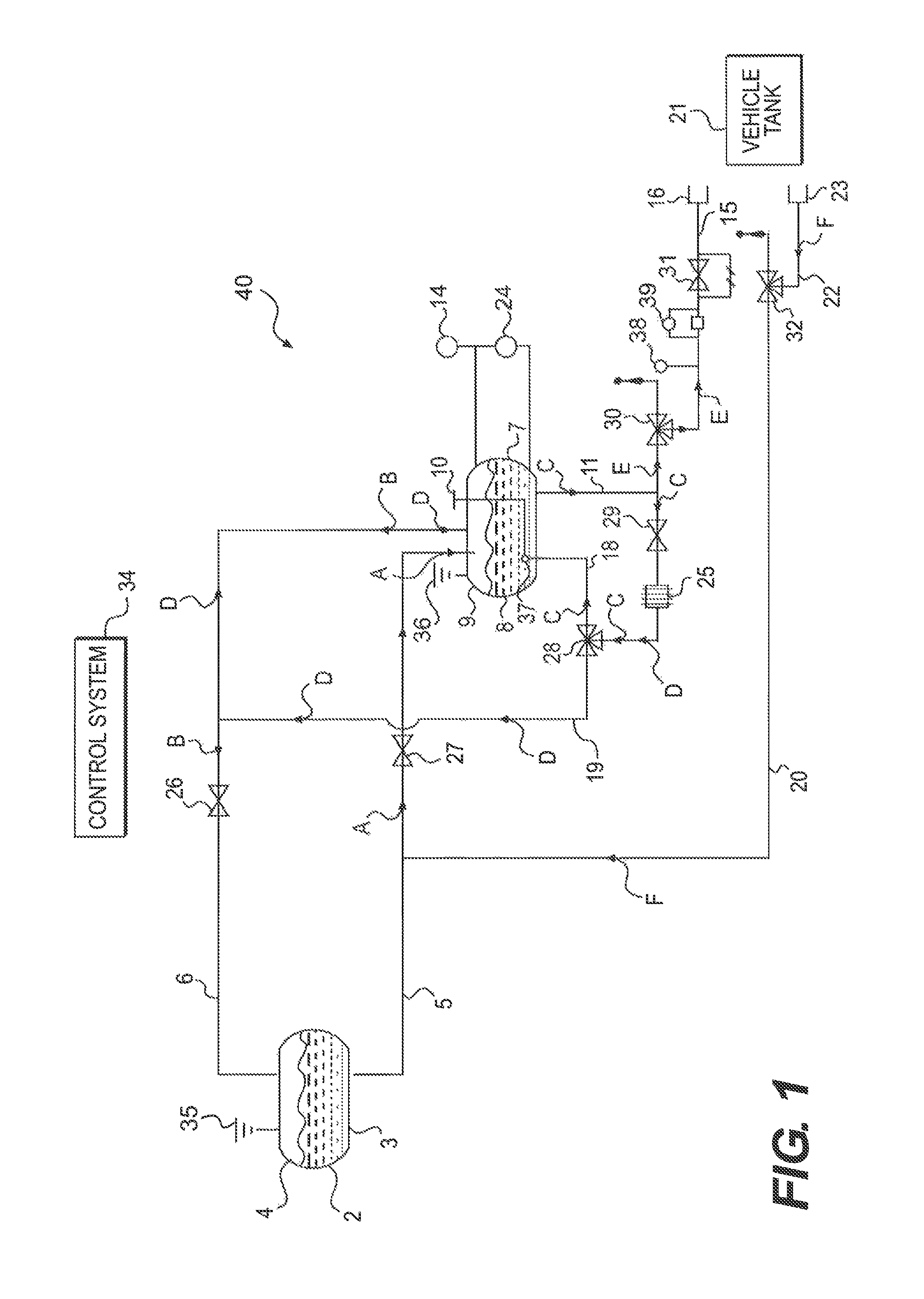
[0018]FIG. 1 depicts a diagrammatic representation of a fluid dispensing system 40, according to an exemplary embodiment of the present disclosure. Although FIG. 1 depicts a fluid dispensing system as including a number of various components, those of ordinary skill in the art will readily recognize that one or more of the depicted components may be replaced and / or eliminated without altering the principles of the present disclosure.

[0019]Dispensing system 40 can be configured to deliver cryogenic liquids, including, but not limited to, LNG. While the present disclosure will refer to LNG as the fluid employed...


PUM


Abstract

A fluid dispensing system may include a first tank configured to contain a first fluid and a second tank configured to contain a second fluid. The system may also include a conditioning system fluidly connected to the second tank. The conditioning system may include at least one conduit fluidly coupled to a lower region of the second tank. The conditioning system may also include a heat exchanger. In addition, the conditioning system may include at least one conduit fluidly coupled to an upper region of the second tank.

Description

FIELD OF THE DISCLOSURE[0001]Embodiments of the present disclosure include dispensers, and more particularly, dispensers for dispensing a fluid, such as a cryogenic liquid, including, but not limited to, liquefied natural gas (LNG).BACKGROUND OF THE DISCLOSURE[0002]Generally, liquefied natural gas presents a viable fuel alternative to, for example, gasoline and diesel fuel. More specifically, LNG may be utilized as an alternative fuel to power certain vehicles and / or power generation plants. Accordingly, there has been an increasing demand for LNG dispensing stations. To meet this demand, a greater number of LNG dispensing stations are being built in increasingly remote locations in order to service the industries that depend on LNG fuel. This presents a range of issues, including station maintenance, safety, and accuracy.[0003]Storing LNG in dispensing stations and vehicle tanks requires specialized equipment because LNG is stored at temperatures of below approximately −200° F. (−1...

Claims


Application Information

Patent Timeline
Patent Type & Authority Patents(United States)
IPC IPC(8): F17C13/02F17C7/02F17C5/00F17C6/00F17C9/00
CPCF17C5/007F17C6/00F17C9/00F17C2201/0104F17C2201/0157F17C2201/032F17C2201/035F17C2201/054F17C2205/0326F17C2205/0332F17C2205/0367F17C2221/033F17C2223/0161F17C2223/033F17C2223/046F17C2225/0161F17C2225/033F17C2227/0107F17C2227/0121F17C2227/0302F17C2250/01F17C2250/032F17C2250/043F17C2250/0408F17C2250/0421F17C2250/0434F17C2250/0439F17C2250/0443F17C2265/032F17C2265/065F17C2270/0105F17C2270/0139F17C2270/05
Inventor MACKEY, MICHAEL
Owner CRYOGENIC IND LLC
Learn More