Missile warhead

a technology of missiles and warheads, applied in the field of missile warheads, can solve the problems of warheads moving in bent lines instead of straight lines, failure of the fuse during penetration, increase in the weight of the weapon system, etc., and achieve the effect of decreasing acceleration and decreasing the load of the penetration fus

Active Publication Date: 2016-02-23
IMI SYST LTD
View PDF44 Cites 4 Cited by
  • Summary
  • Abstract
  • Description
  • Claims
  • Application Information

AI Technical Summary

Benefits of technology

[0018]1. High durability due to reduced stress while penetrating several / layered structural targets, without a significant increase in weight.
[0028]Because of the same mechanism the ribs reduce the movement curvature, e.g., the J Effect, and so allow the warhead to penetrate thicker targets and / or a number of walls in a substantially straight movement in case of non-perpendicular strikes of wall targets. The reduced movement curvature decreases the side forces and torques on the warhead, and thus allows a greater chance of survival and greater reliability of the warhead and the fuse during and after target penetration.

Problems solved by technology

Such forces create a rotation moment (torque) around the center of mass of the warhead and cause the warhead to move in a bent line instead of a straight line, or to ricochet, if the warhead hits at shallower impact angles.
This effect is called the J Effect which causes some or all of the following problems: (a) the warhead rotates during target penetration, generating considerable loads on the warhead that may lead to the structural failure of the warhead, (b) the warhead ricochets off the target when the strike angles are shallow, (c) the warhead potential penetration depth of a target is decreased due to bent penetration line, and (d) lateral accelerations acting on the fuse located in the rear part of the warhead increase; such accelerations may cause failure of the fuse during penetration.
This approach has several limitations including an increase in the weight of the weapon system, which is undesirable, reduction of the internal volume for the explosive charge in the warhead and a more complicate design of the penetration fuse.
As a result, the cost of the warhead-fuse system increases and its effectiveness decreases.
This kind of nose reduces the J Effect by creating an opposing force at the beginning of the penetration which balances the moment (torque), but creates much bigger drag forces during the penetration.
As a result of the bigger drag forces, some or all of the following problems may develop:Reduced penetration capability, especially in perpendicular penetration angles because of the configuration of the nose which significantly increase the drag forces on it.Increase of the accelerations along the axis of the warhead, due to the increased resistance or drag forces, which also negatively affect the warhead and the fuse.
Thus, warheads of this kind are limited to strikes at relatively shallow angles and into relatively thin targets only.

Method used


Image

  • Missile warhead
  • Missile warhead
  • Missile warhead

Examples


second embodiment

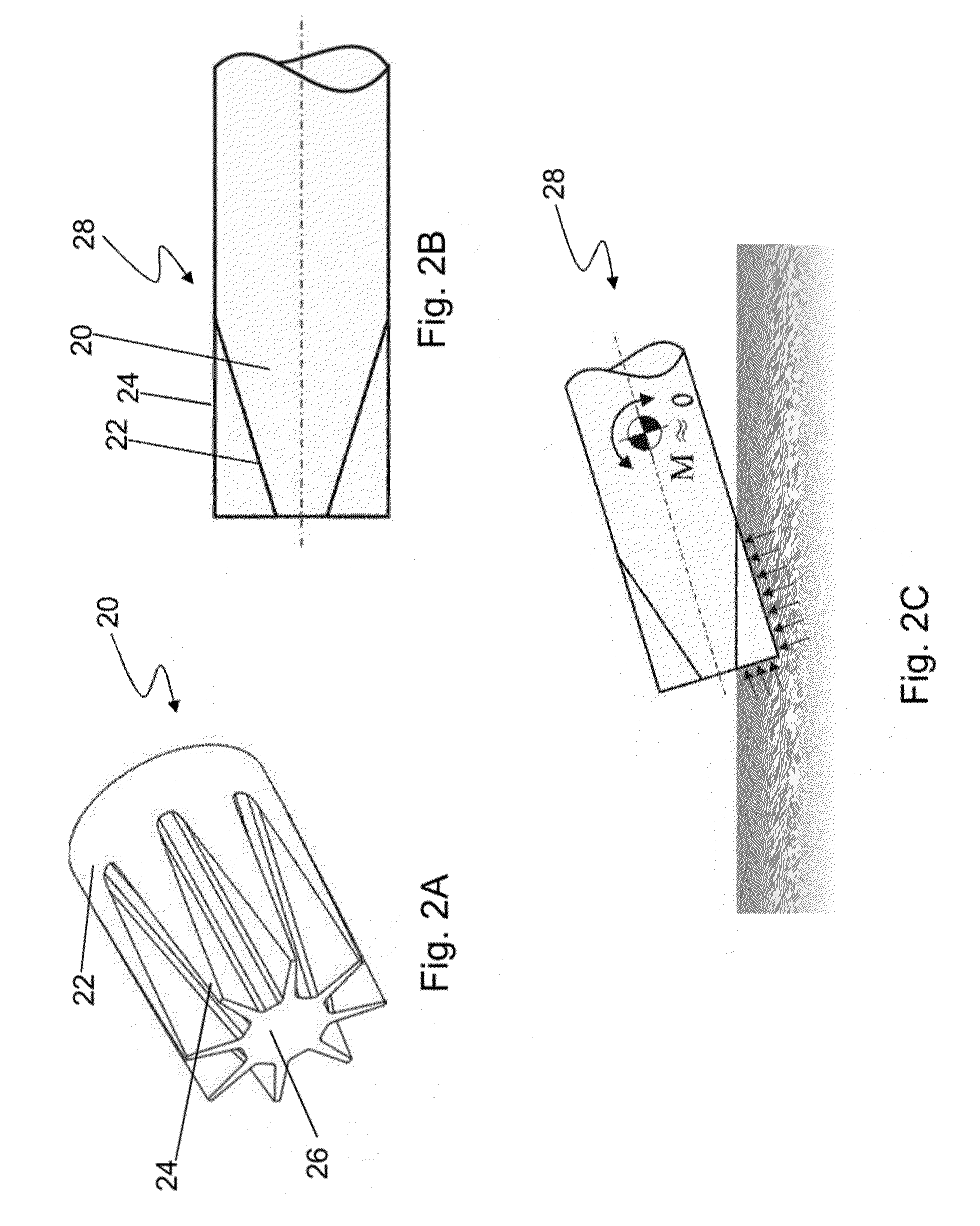
[0078]FIG. 2A is a perspective view of a warhead nose 20 in accordance with the present invention. Warhead nose 20 has a relatively short conical body 22, relatively thin ribs 24 along the outer surface of the conical body 22, and a flat tip 26. Ribs 24 are relatively thin to allow penetration into and splitting of the target material without bouncing from the target surface.

[0079]As seen in FIG. 2A, nose 20 has a conical body 22, however, the structural profile of the nose 20 together with the ribs 24 is not of a cone, but of a non-solid cylinder which results from the shape and width of the ribs 24.

[0080]FIG. 2B is a cross sectional side-view of a warhead 28 having the warhead nose 20 of FIG. 2A.

[0081]As can be seen in the figure, unlike the tapered cross section of nose 10, nose 20 has a rectangular cross section.

[0082]FIG. 2C illustrates the warhead of FIG. 2B at an initial stage of penetration at a relatively low strike angle of between 0° to 45° relative to the plane of the ta...

fourth embodiment

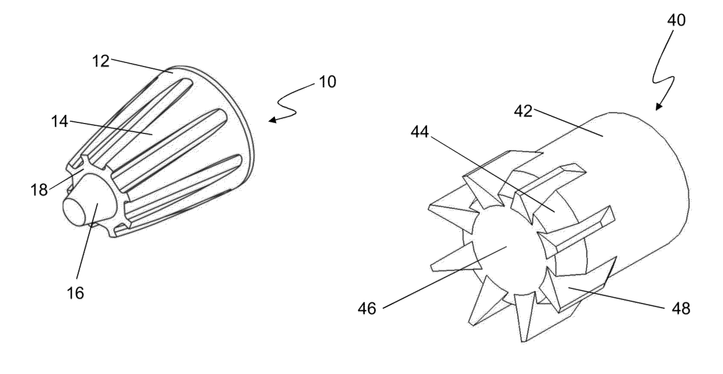
[0084]FIG. 4 is a perspective view of a warhead nose 40 in accordance with the present invention. The body of warhead nose 40 includes a relatively long cylindrical section 42 and a relatively short conical section 44 with flat tip 46. Warhead nose 40 contains ribs 48 partially extending from the outer surface of the cylindrical section 42 and partially from the conical section 44. The outer circumference of the nonsolid cylinder created by the ribs is wider than the circumference of the cylindrical body 42 of the nose 40. In this case, the protruding ribs create a non-solid cylindrical shape the diameter of which is greater than the actual diameter of the cylindrical section of the warhead. This design keeps the warhead from bouncing off the target surface when the warhead is installed in the missile, in a sub-caliber configuration (the warhead is an internal part of the missile), when relatively shallow strike angles (0 to 45) are reached. The ribs are first to hit the target and ...


PUM


Abstract

A warhead nose comprises a conical / ogive body having an outer surface with a top circumference and base circumference, and ribs extending along the outer surface of the conical / ogive body tapering so that the circumference around the ribs is smaller than or equal to the circumference of the base, the warhead nose dimensions are determined by the following relations:E≤D,⁢15⁢D≤F≤2⁢⁢D,⁢G≤15⁢D,⁢120⁢D≤H≤12⁢D,⁢I≤25⁢Dwhere,D is maximum nose diameter; E is external diameter of the ribs; F is length of the ribs along the nose; G is minimal width of the ribs; H is height of the rib protrusion; and I is the minimal width of the rib at the adjoining point with the nose.

Description

CROSS REFERENCE TO RELATED APPLICATIONS[0001]This application is a 371 U.S. National Stage of International Application No. PCT / IL2013 / 000035, filed Mar. 24, 2013, which claims priority to Israeli Patent Application No. 219010, filed Apr. 3, 2012. The disclosures of the above applications are incorporated herein by reference.FIELD OF THE INVENTION[0002]The present invention relates to missile warheads especially unguided warheads designed to penetrate hard targets and in particular multiple wall targets.BACKGROUND OF THE INVENTION[0003]Warheads are often required to penetrate hard concrete or steel targets of either one or multiple layers (walls) and to explode afterwards inside a target cavity. Such warheads have an ogive or a conical nose that assists the penetration by reducing the resistance forces.[0004]This type of warhead is typically made of three sections: (1) a front section, or nose, which is usually in the shape of an ogive or cone; (2) the main section which includes t...

Claims


Application Information

Patent Timeline
Patent Type & Authority Patents(United States)
IPC IPC(8): F42B12/08F42B12/04F42B12/20F42B12/06
CPCF42B12/08F42B12/04F42B12/06F42B12/20
Inventor AMON, JACOBSCHWARTZ, ANNABRANDEIS, YARON
Owner IMI SYST LTD
Why Eureka
Try Eureka