Tension systems and methods of use

a technology of tensioning system and cable, which is applied in the direction of resilient force resistors, gymnastic exercises, weights, etc., can solve the problems of user fatigue, inability to complete the exercise with the selected weights, and interruption of critical exercise timing, so as to improve muscle strength and muscle strength. the effect o

Inactive Publication Date: 2016-03-01
PERSONAL TRAINER
View PDF47 Cites 11 Cited by
  • Summary
  • Abstract
  • Description
  • Claims
  • Application Information

AI Technical Summary

Benefits of technology

[0010]A cable is attached directly or indirectly at or near one end of the lever mechanism or screw member. Tension on the cable is increased or decreased depending on the position of the weight (which may be on a carriage) on the lever member.
[0025]It is also an object of the present invention to provide cable-based exercise or strength improvement systems and methods capable of acting as an automatic spotter to monitor and automatically reduce or eliminate tension (weight) on the cable system if user fatigue is detected.

Problems solved by technology

Because of the fatigue factor, the user may become exhausted and unable to complete the exercise with the selected weights.
This results in at least two problems.
This may interrupt critical timing in the exercise.
Second, the fatigue experienced by the user is dangerous in that the weights may be dropped or mishandled, resulting in injury to the user.
However, a second person is not always available which may expose the weight lifter to unnecessary risk of injury.
Unfortunately, none of these inventions provides a simple, compact weight resistance system that has the combined capabilities of (a) providing variable adjustability in the amount of tension (weight) placed on the cable, including automatic tension adjustment (reduction or release) near the end of a set of repetitions when the user is becoming fatigued; and (b) providing an automatic spotting / safety function without the need for a second person.

Method used


Image

  • Tension systems and methods of use
  • Tension systems and methods of use
  • Tension systems and methods of use

Examples


Embodiment Construction

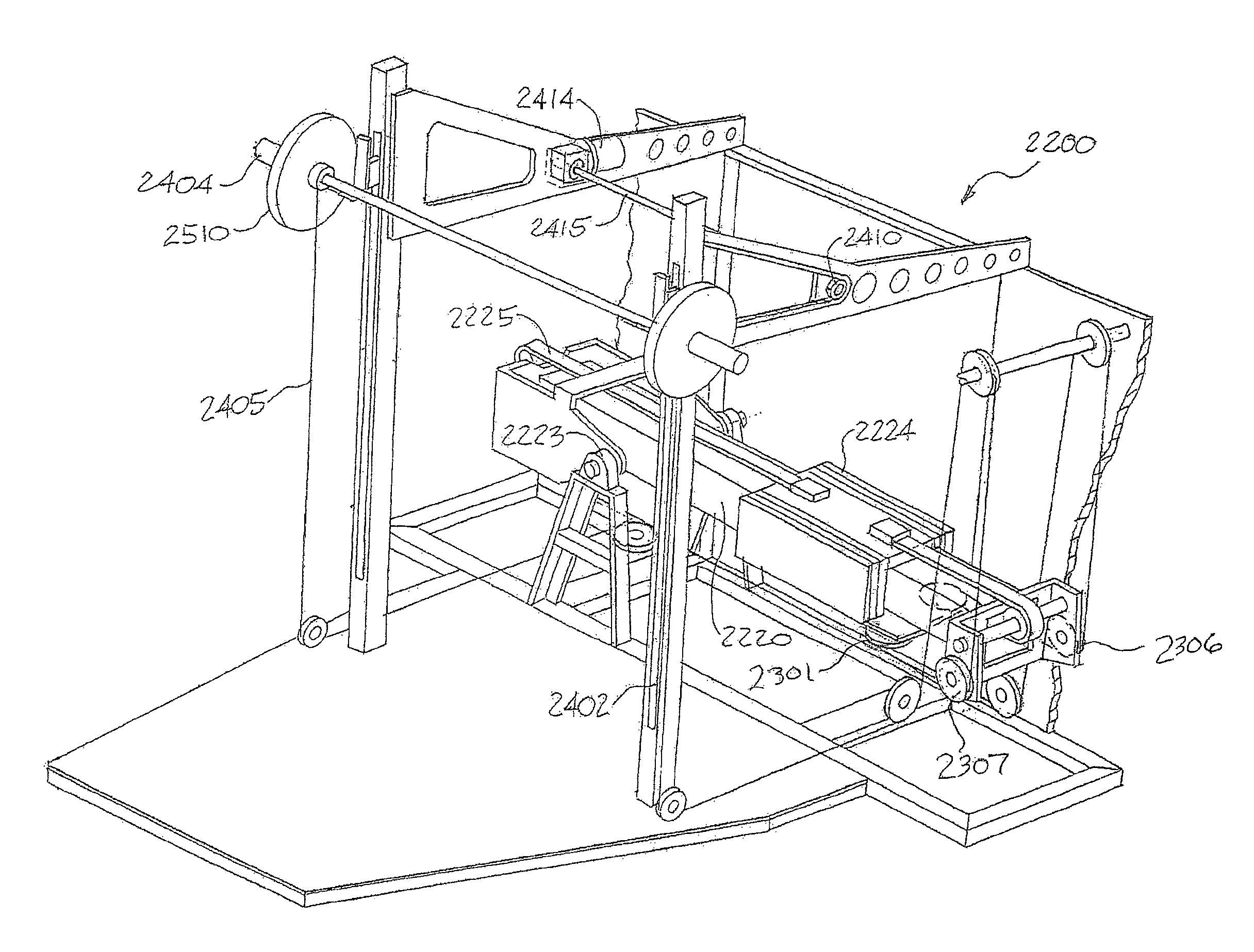
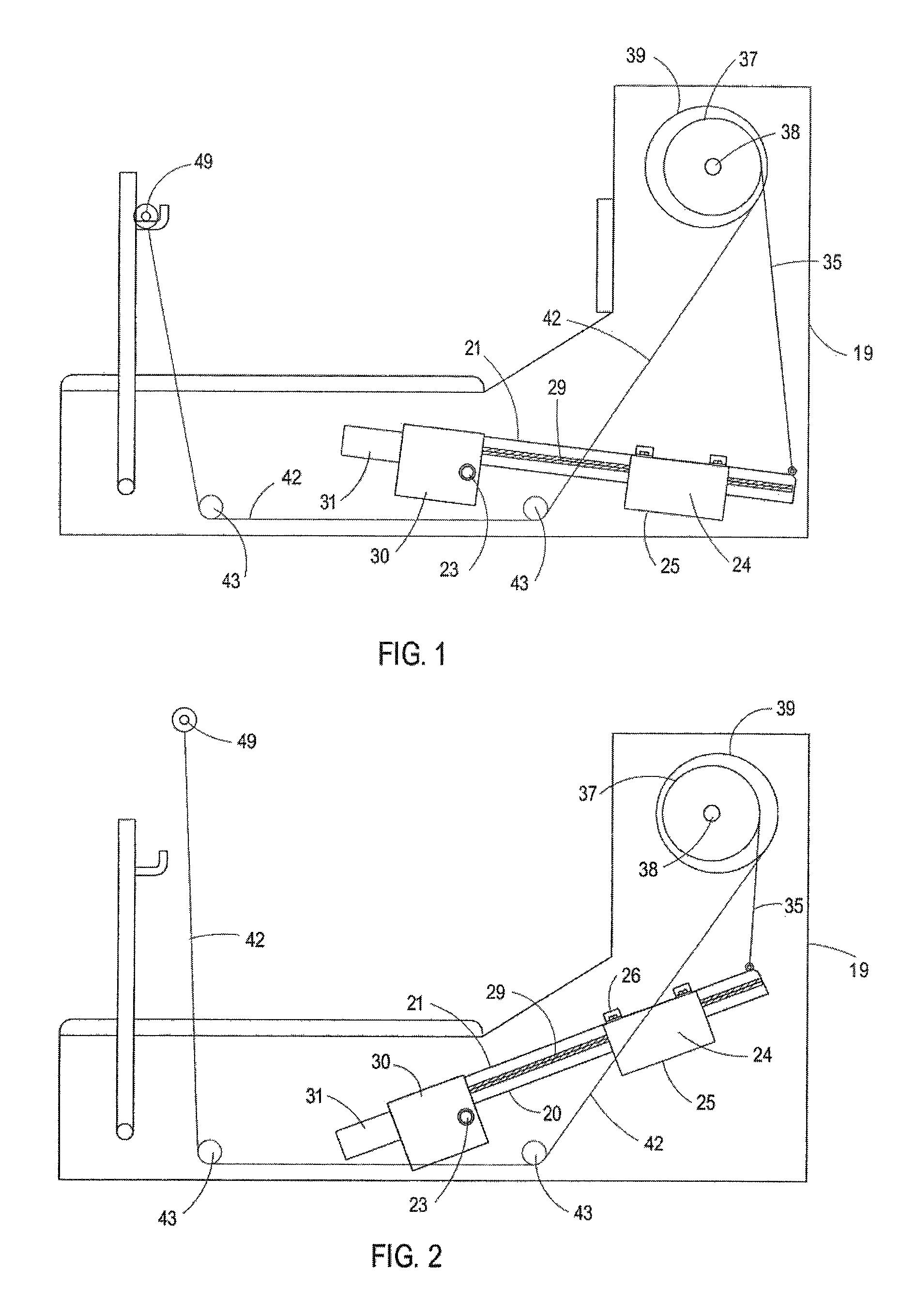
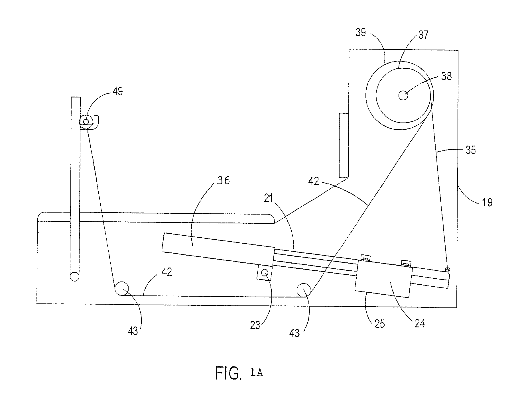
[0054]Referring to the drawings wherein like reference characters designate like or corresponding parts throughout the several views, and referring particularly to the exemplary embodiments of FIGS. 3-9, it is seen that these embodiments include a leverage system for installation inside a cabinet or frame 19 comprising an elongated member 20 having a track 21 (see FIG. 9) for supporting a movable carriage 25 using wheels, guides or other supports 26. At least one weight 24 is provided with, on or made a part of carriage 25. Member 20 is pivotally mounted at 23 so that it may operate as a lever. It is to be appreciated that in other embodiments (such as the embodiment illustrated in FIG. 15), that weight 24 may be movably provided directly on lever member 20.

[0055]In the embodiments illustrated in FIGS. 3-9, a threaded screw 29 is provided in parallel with lever member 20. A drive motor 30 is provided, preferably at one end of screw 29, to impart rotation to it. A threaded bore (see ...


PUM


Abstract

Machines, apparatuses, systems and methods for providing adjustable tension to a cable system using a pivotally mounted leverage mechanism that employs an adjustably positionable weight. Embodiments are used in exercise and other muscle strengthening devices, and may include an electronic control system for monitoring, recording a user's progress, and for altering or releasing tension to the cable system based on feedback from the user. Embodiments include a user interface for inputting information for particular exercises or workouts, as well as outputting / downloading information following exercises or workouts. Other embodiments allow adjustment to the starting point of the lifting bar so that such machines may be used for bench presses, squats, cleans or curls.

Description

RELATED APPLICATIONS[0001]This application is a continuation-in-part of U.S. patent application Ser. No. 12 / 606,123, filed Oct. 26, 2009, which is incorporated herein by this reference in its entirety.FIELD OF THE INVENTION[0002]The present invention relates to cable tensioning systems, and more particularly to unique and compact adjustable cable tensioning systems, apparatus, machines and related methods for use in such applications as weight training, exercising, muscle toning, muscle development, and the like.DISCUSSION OF THE BACKGROUND[0003]Weight training is a common form of exercise to increase strength and build muscle. A typical weight lifting apparatus includes a bar that is capable of receiving weights on both ends. The user places the desired weights on the bar, and then lifts the bar so that the weights act as resistance to the muscles of the user. A certain number of repetitions of the lift are performed in order to complete a particular exercise. Typically, the most b...

Claims


Application Information

Patent Timeline
Patent Type & Authority Patents(United States)
IPC IPC(8): A63B21/05A63B24/00A63B21/06A63B21/00A63B23/12A63B21/08A63B71/00A63B23/08A63B23/04A63B21/02A63B21/005A63B21/002A63B21/062A63B21/078A63B23/035
CPCA63B21/06A63B21/078A63B21/151A63B21/154A63B23/12A63B21/159A63B21/00076A63B71/0054A63B24/0062A63B21/0632A63B21/0783A63B23/03525A63B21/4043A63B21/4035A63B21/0628A63B23/0494A63B23/085A63B2023/0411A63B2024/0068A63B2071/0072A63B2225/20A63B21/002A63B23/1236A63B21/4029
Inventor LEMOS, ROBERT, F.ALLDRIN, KENFIELD
Owner PERSONAL TRAINER
Why Eureka
Try Eureka