
Integrated puncture repair kit

a puncture repair and integrated technology, applied in the direction of transportation and packaging, vehicle maintenance, other domestic objects, etc., can solve the problems of difficult to distinguish which one should be coupled to an object, complicated internal piping, and impair assembly work efficiency, so as to enhance assembly work efficiency, simplify piping and structure, and improve operability

Inactive Publication Date: 2016-03-01
SUMITOMO RUBBER IND LTD
View PDF17 Cites 1 Cited by
  • Summary
  • Abstract
  • Description
  • Claims
  • Application Information

AI Technical Summary

Benefits of technology

This patent describes an integrated puncture repair kit that includes a extraction cap with two flow passages: one for air and one for puncture repair. These passages can be switchably coupled to the inlet mouth using a switching means. The simplified piping and structure of the kit reduces the number of hoses, facilitates downsizing and cost reductions. The kit also includes a first on-off valve to close the second flow passage and prevent leakage of the puncture repair fluid during storage. The technical effects of this invention are improved assembly work efficiency, simplified structure, enhanced operability, and prevention of leakage.

Problems solved by technology

The above puncture repair kit, however, includes the two hoses (f, g), and hence it is difficult to distinguish which one should be coupled to an object.
Additionally, the transfer switch (d) is disposed separately, resulting in complicated internal piping.
The complicated internal piping impairs assembly work efficiency and makes it difficult to achieve downsizing and cost reductions of the integrated puncture repair kit.
The use of the two hoses (f, g) is also obstructive to the downsizing and cost reductions.

Method used


Image

  • Integrated puncture repair kit
  • Integrated puncture repair kit
  • Integrated puncture repair kit

Examples


Embodiment Construction

[0027]An embodiment of the present invention will be described in detail below.

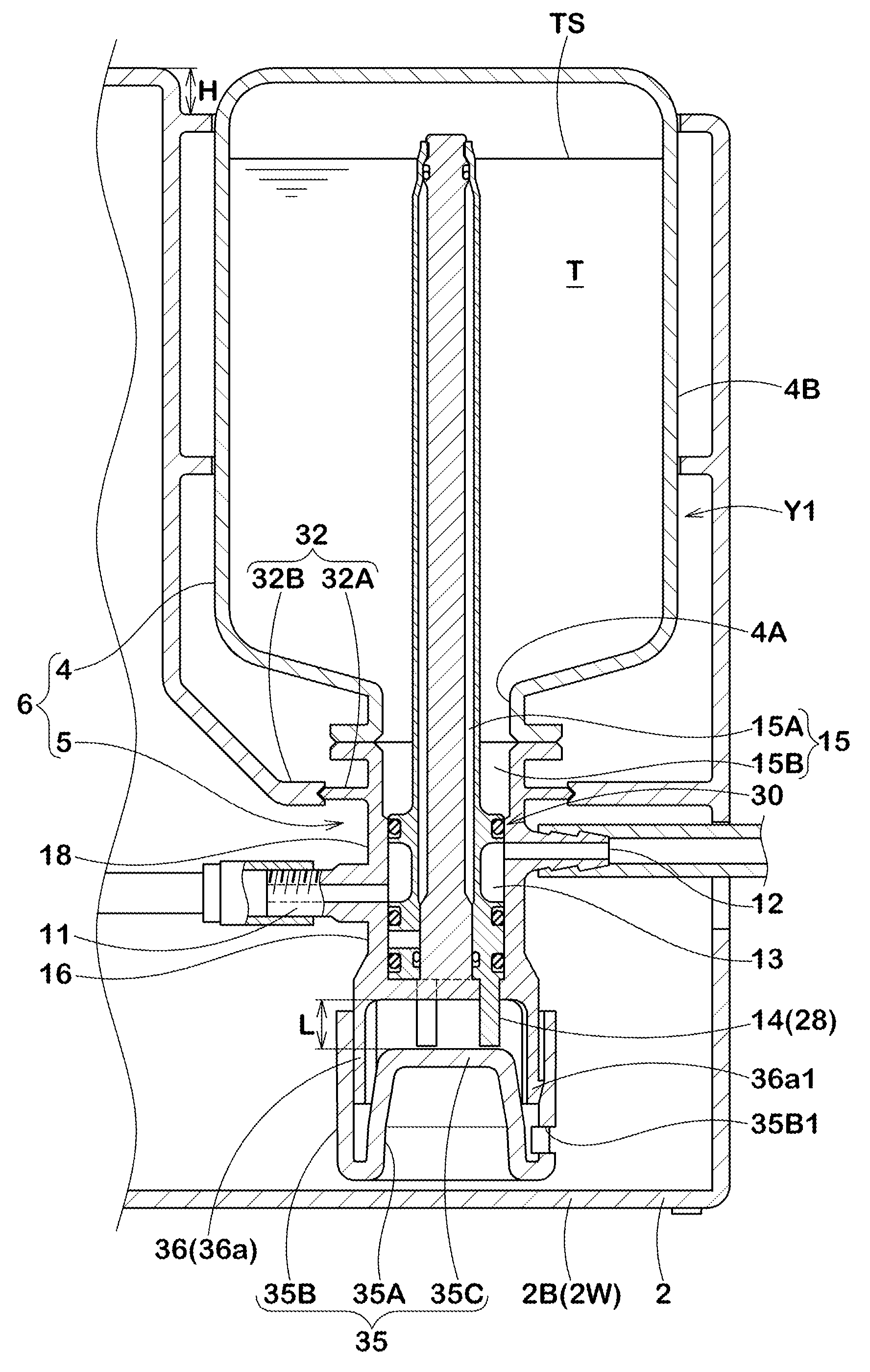
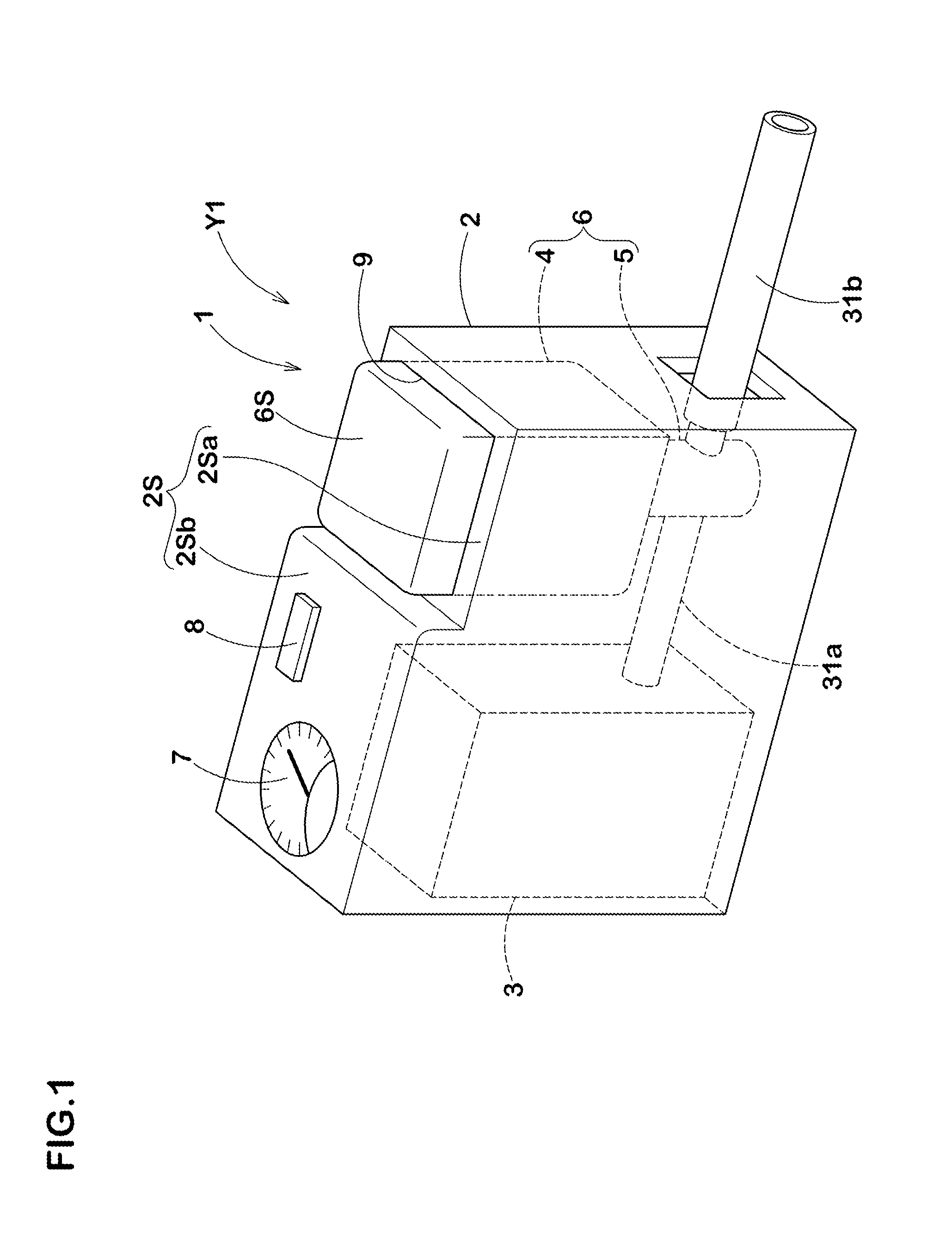
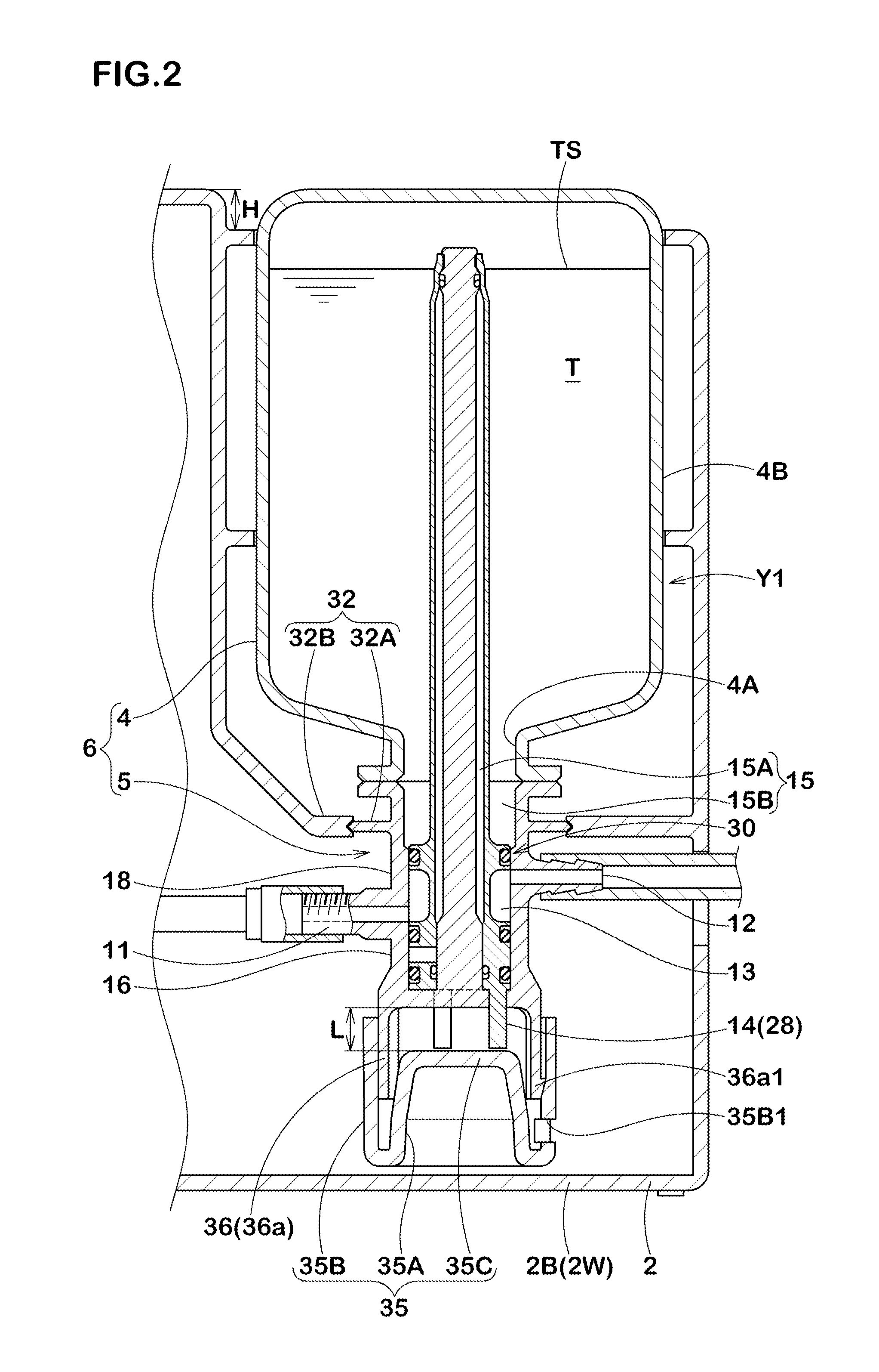
[0028]Referring to FIG. 1, an integrated puncture repair kit 1 according to the present embodiment includes a housing case 2, a compressor 3 to discharge compressed air, and a bottle unit 6. The compressor 3 and the bottle unit 6 are housed and held in a lateral array in the housing case 2. The bottle unit 6 includes a bottle container 4 storing a puncture repair fluid T, and an extraction cap 5 to be attached to a mouth portion 4A of the bottle container 4.

[0029]No special restriction is imposed on the compressor 3, and ones having a well-known structure to be operated by a car battery are suitably employed.

[0030]The housing case 2 has a rectangular box shape. In the present embodiment, an upper surface portion 2Sa of an upper surface 2S of the housing case 2 on the side on which the bottle unit 6 is housed is defined by a stepped surface lower than an upper surface portion 2Sb on the side on which the c...


PUM

PropertyMeasurementUnit
diameteraaaaaaaaaa
inner diameteraaaaaaaaaa
dimensionaaaaaaaaaa

Abstract

An extraction cap of an integrated puncture repair kit is provided with: an intake unit for taking compressed air coming from a compressor into the extraction cap; an outlet unit for taking the intaken compressed air or both compressed air and a puncture repair solution to outside the extraction cap; a dedicated air flow path that ordinarily connects to the intake unit and provides conduction from the inlet unit to the outlet unit without passing through a bottle container; a dedicated puncture repair flow path comprising a first flow path section that is connected by a switching means to the intake unit instead of the dedicated air flow path and providing conduction from the intake unit into the bottle container, and a second flow path section providing conduction from inside the bottle container to the intake unit; a first on-off valve that is interposed in the second flow path section and ordinarily closes the first flow path section; and the switching means, which is actuated by downward pressing of a bottle unit and connects the intake unit switching from the dedicated air flow path to the dedicated puncture repair flow path, and also releases the first on-off valve to close the second flow path section.

Description

TECHNICAL FIELD[0001]The present invention relates to an integrated puncture repair kit that is switchable between puncture repair and charging only compressed air so as to enhance versatility and improve operability.BACKGROUND ART[0002]As an integrated puncture repair kit that is switchable between puncture repair and charging only compressed air so as to enhance versatility, one described in the following patent document 1 is known. As conceptually shown in FIG. 8, the integrated puncture repair kit includes a compressor (b), a bottle unit (c), and a manual transfer switch (d) interposed between the compressor (b) and an extraction cap (c2), which are respectively disposed in a housing case (a). The bottle unit (c) includes a bottle container (c1) storing a puncture repair fluid therein, and the extraction cap (c2) attached to a mouth portion of the bottle container (c1).[0003]The extraction cap (c2) includes an inlet mouth portion (e1) to take in compressed air, and an outlet mou...

Claims


Application Information

Patent Timeline
Patent Type & Authority Patents(United States)
IPC IPC(8): B60C25/00B60S5/04B29C73/16B29L30/00
CPCB60C25/16B29C73/166B60S5/04B29L2030/00
Inventor TANIGUCHI, NORIOKONO, TSUTOMU
Owner SUMITOMO RUBBER IND LTD
Learn More