

Integrated flat tire repair kit
- Summary
- Abstract
- Description
- Claims
- Application Information
AI Technical Summary
Benefits of technology
Problems solved by technology
Method used
Image

Examples
Embodiment Construction
[0040]An embodiment of the present invention is described in detail below.
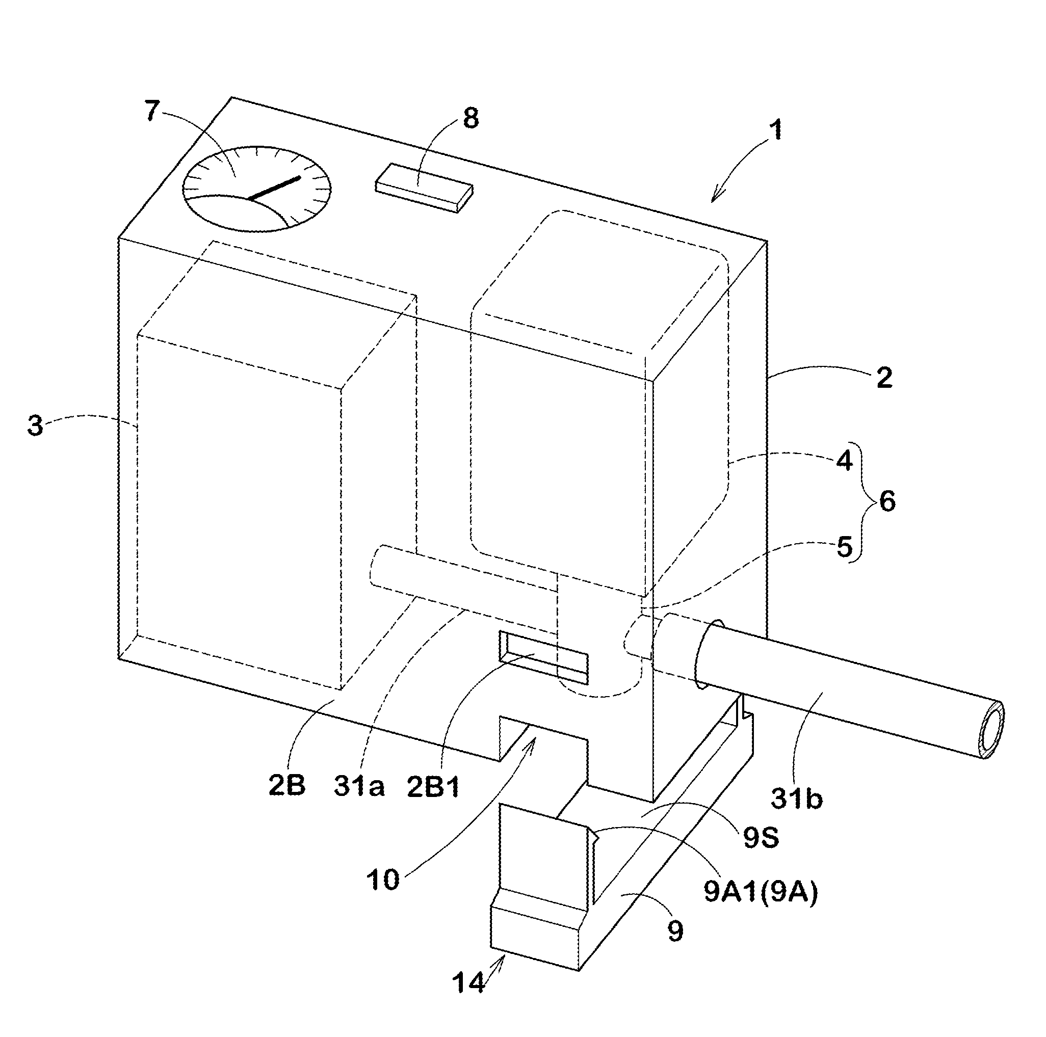
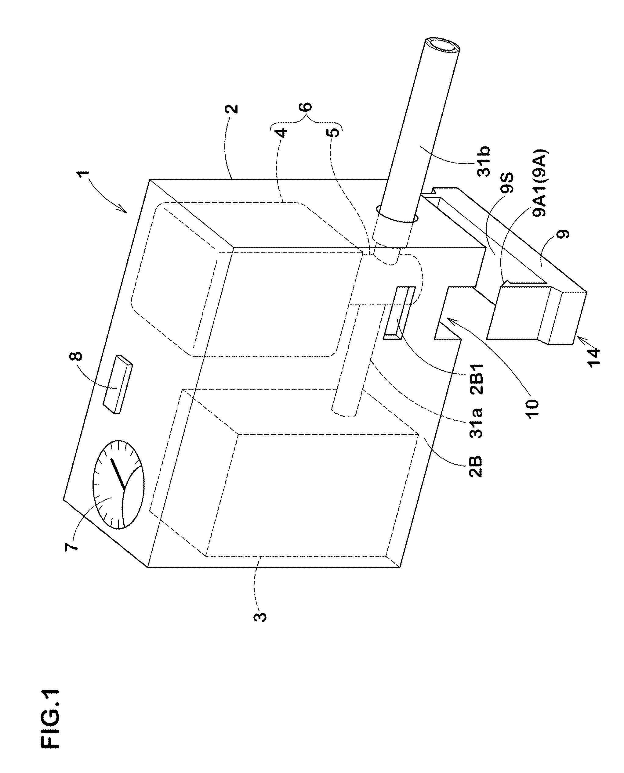
[0041]FIG. 1 is a perspective view showing an embodiment of an integrated flat tire repair kit 1 according to the present embodiment. The integrated flat tire repair kit 1 includes a housing case 2. The housing case 2 houses and holds therein, a compressor 3 to discharge compressed air, and a bottle unit 6 with an extraction cap 5 secured to a bottle container 4 storing a puncture repair fluid T. The compressor 3 and the bottle unit 6 are disposed in, for example, a lateral direction.
[0042]No specific restriction is imposed on the compressor 3, and one having a well-known structure to be operated by an automobile battery is suitably employed.
[0043]The housing case 2 has a rectangular box shape. In the present embodiment, a pressure gauge 7 and a power switch 8 are disposed on an upper surface of the housing case 2.
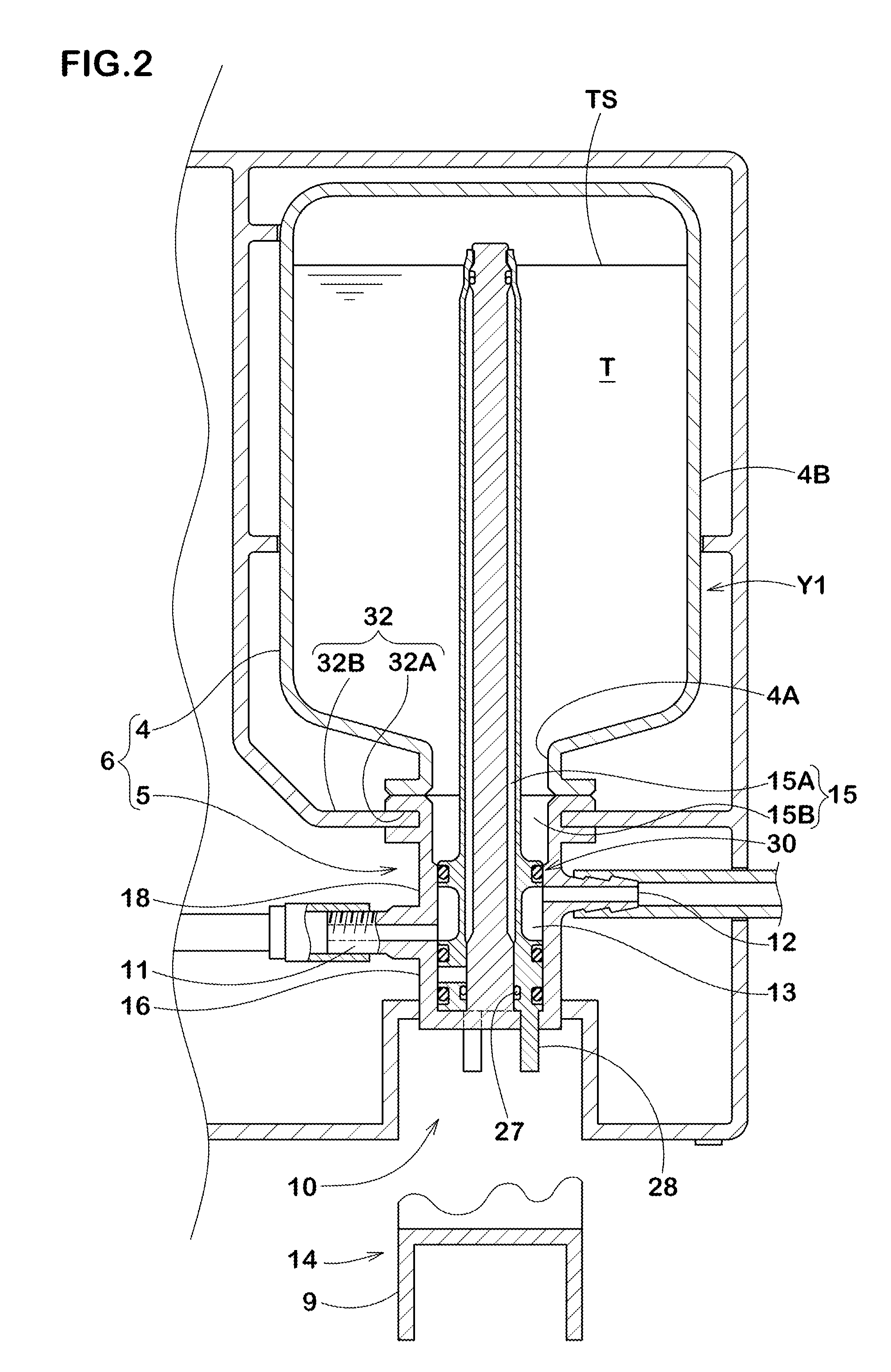
[0044]As shown in FIG. 2, the bottle unit 6 is made up of the bottle container 4 and the extracti...
PUM
| Property | Measurement | Unit |
|---|---|---|
| Time | aaaaa | aaaaa |
| Diameter | aaaaa | aaaaa |
Abstract
Description
Claims
Application Information