Angular velocity-controlled pontoon propulsion system

a technology of angular velocity and propulsion system, which is applied in the direction of marine propulsion, special-purpose vessels, vessel construction, etc., can solve the problems of stability and efficiency of forward and backward sliding of pontoons, and achieve the effects of increasing the user's control over the invention, increasing propulsion, and increasing stability

Active Publication Date: 2016-03-01
FARMER JEROME C
View PDF71 Cites 1 Cited by
  • Summary
  • Abstract
  • Description
  • Claims
  • Application Information

AI Technical Summary

Benefits of technology

[0005]The present invention provides various embodiments of an apparatus that produces forward motion when a user standing on two pontoons shifts her or her weight between the pontoons, causing angular and / or vertical motion between the pontoons as viewed from fore or aft. The user's movement causes the pontoons to move generally vertically, but may also move laterally as controlled by the invention's mechanical connections. The pontoons are generally kept parallel to each other. The change of the relative position of the two pontoons, as viewed from the fore or aft, may be used to control a propeller. In some embodiments, sensors, either electrical or mechanical, continuously sample the position of the pontoons, either directly by measuring the pontoons or by measuring mechanical connections to the pontoons. The speed at which the user is moving the pontoons by shifting his or her weight between them is calculated, including accounting for the movement of the water, and the calculated angular speed is used as an input to control the rate of rotation of a propeller. The faster the movement, the more propulsion, although the relationship may not be linear. There may also be a rotational-velocity sensor on the propeller shaft that provides feedback to help stabilize the apparatus and control the propeller's speed. Resistance to the rotation of the mechanical joints may be controlled by the user, thereby determining the physical force required to change the relative position of the pontoons. Fins may add additional stability. An electrical system, including buttons, visual displays, and audio signals, may be included to increase the user's control over the invention.

Problems solved by technology

The forward and backwards sliding of pontoons has drawbacks of stability and efficiency.

Method used


Image

  • Angular velocity-controlled pontoon propulsion system
  • Angular velocity-controlled pontoon propulsion system
  • Angular velocity-controlled pontoon propulsion system

Examples


Embodiment Construction

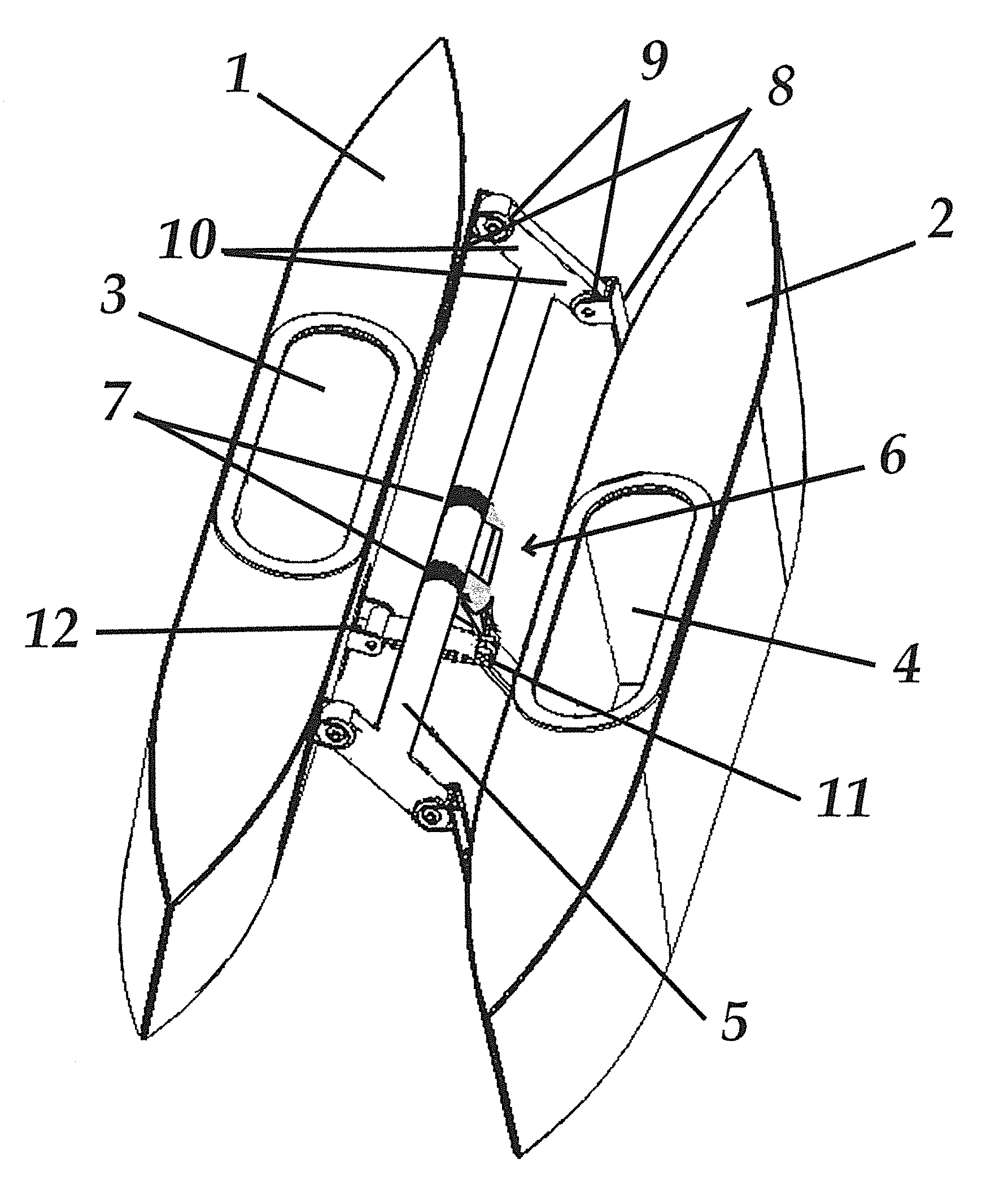
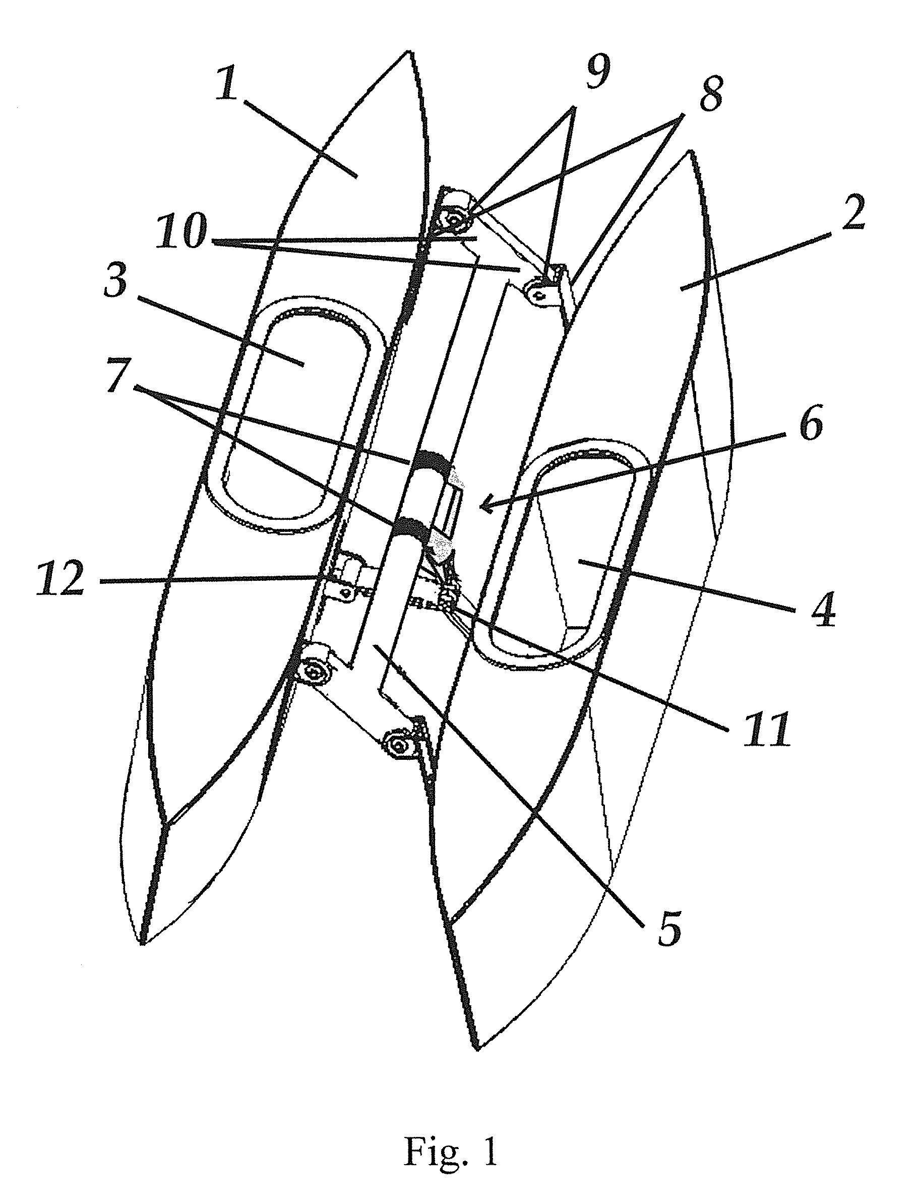
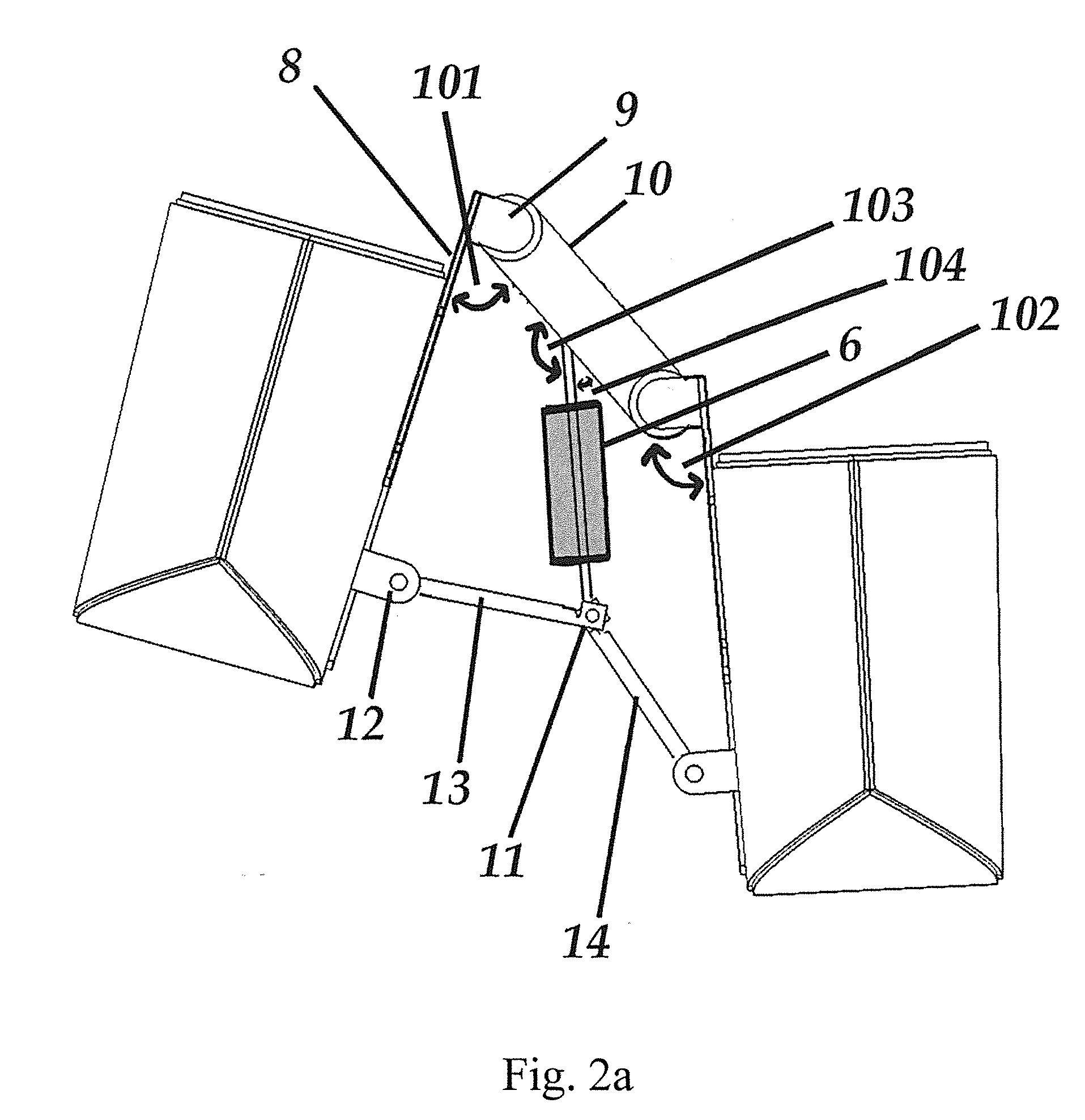
[0025]The present invention provides an apparatus for floatation and propulsion of a user on a body of water. The user stands upon two pontoons with a foot in a chamber in each pontoon. When the user shifts his or her weight between the pontoons, the angle of the pontoons relative to the horizon changes as viewed from fore or aft of the invention. A mechanical apparatus keeps the pontoons longitudinally parallel, so the angles that change are on a longitudinal axis (thus viewed from the fore or aft). Not only do the pontoon angles change relative to the horizon, but also the relative position of the tops of the pontoons changes. The invention provides a mechanical connection between the pontoons that fixes the geometric relation between the pontoons and also adds stability. As the user shifts his or her weight between the pontoons, the change of position between the pontoons is sensed, either directly or indirectly, and the rate of this change is used to control the force of the pro...


PUM


Abstract

An apparatus for floatation and propulsion of a user on a body of water, with the user in a standing position, includes two pontoons, a mechanical connection of the pontoons and a propulsion system responsive to vertical articulation of the pontoons.

Description

CROSS-REVERENCE TO RELATED APPLICATIONS[0001]This application claims priority to U.S. provisional patent application Ser. Nos. 61 / 870,509, filed Aug. 27, 2013, and 61 / 933,274, filed Jan. 29, 2014, which are incorporated herein in their entirety.FIELD OF THE INVENTION[0002]The present invention relates generally to apparatus for floatation and propulsion of a user on a body or water.BACKGROUND OF THE INVENTION[0003]When people use devices to stand on the water, they usually either use the movement of the water (i.e. surfing), the wind (i.e. windsurfing or kite surfing) or their arms (i.e. standup paddleboarding) to propel them. Less commonly, people have used the forward and backward sliding movement of pontoons to provide motion.[0004]The forward and backwards sliding of pontoons has drawbacks of stability and efficiency. It requires the user to move his or her legs forward and backwards at the same time as balancing as waves come from all directions.SUMMARY OF THE INVENTION[0005]Th...

Claims


Application Information

Patent Timeline
Patent Type & Authority Patents(United States)
IPC IPC(8): B63B35/83B63H23/00B63H5/07B63B1/14B63H16/18B63B34/56
CPCB63B35/83B63B1/14B63H5/07B63H16/18B63B2001/145B63H2016/185B63B34/56
Inventor FARMER, JEROME, C.
Owner FARMER JEROME C
Why Eureka
Try Eureka