Gravity-assisted geomagnetic generator

a gravity-assisted, geomagnetic generator technology, applied in the direction of dynamo-electric machines, dynamo-electric components, electrical equipment, etc., can solve the problems of inability to meet the needs of dynamo-electric generators. to achieve the effect of increasing the degree of magnetism, reducing the h a gravity-assisted geomagnetic generator and gravity-assisted geomagnetic generator technology, applied in the field of gravity-assisted geomagnetic generator technology, applied in the field of gravity-assisted geomagnetic field, which is applied in the field of gravity, and dynamical field of gravity-assisted magnetic field field

Inactive Publication Date: 2012-04-26
RAGHUPRASAD PUTHALATH KOROTH
View PDF2 Cites 9 Cited by
  • Summary
  • Abstract
  • Description
  • Claims
  • Application Information

AI Technical Summary

Benefits of technology

[0011]A geomagnetic power generating apparatus has a guide means, one or more moving permanent magnets, a plurality of coils and a battery or series of batteries. In the one or more moving permanent magnets, each permanent magnet has a north polarity at a first end and a south polarity at the opposite second end. The one or more magnets are located and guided along a guide path by the guide means. The plurality of coils has each coil positioned around the guide means, encircling both the guide means and the guide path along which one or more permanent magnets move. Each coil has a cross section having an increasing number of windings extending from a minimal winding at first end to a maximum winding at second end. The battery or a series of batteries is connected to the plurality of coils. When the one or more permanent magnets are moved, with one magnet approaching toward each coil and as the N or S end of the magnet approaches inside the coil an electric current is created along with a magnetic field having a like polarity at the narr...

Problems solved by technology

The biggest problem with such devices is that the source of energy is not always constant.
Water currents, wind and solar energy often-times are not predictable and, in the case of solar power, it is not available during the night.
Unlike solar power, which needs...

Method used


Image

  • Gravity-assisted geomagnetic generator
  • Gravity-assisted geomagnetic generator
  • Gravity-assisted geomagnetic generator

Examples


Embodiment Construction

[0040]The following language describes the best presently contemplated mode or modes of carrying out the invention. This description is made for the purpose of illustrating the general principles of the invention and should not be taken in a limiting sense. The scope of the invention is best determined by reference to the appended claims. The reference numerals as depicted in the drawings are the same as those referred to in the specification. For purposes of this application, the various embodiments illustrated in the figures each use the same reference numeral for similar components. The structures employ basically the same components with variations in location or quantity thereby giving rise to the alternative constructions in which the inventive concept can be practiced.

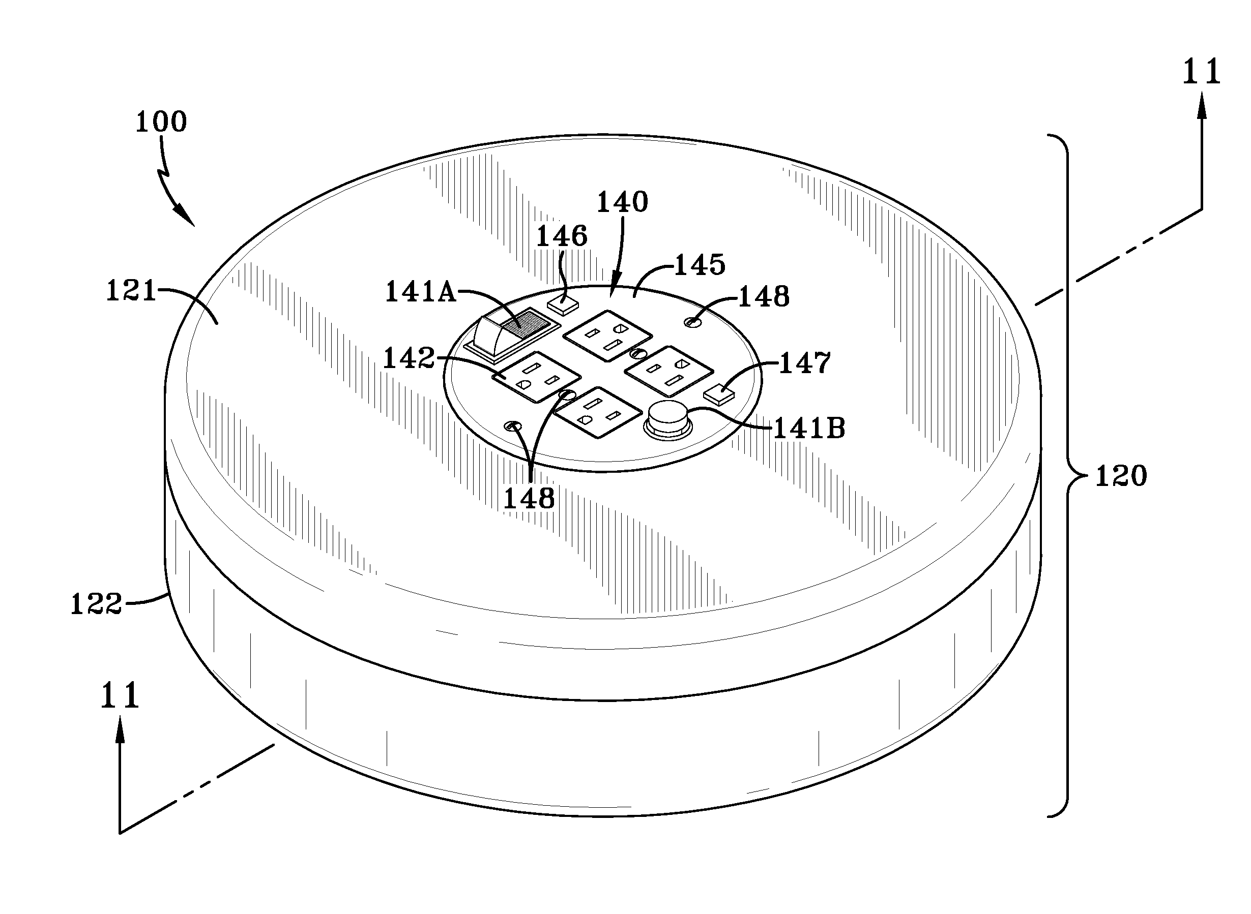
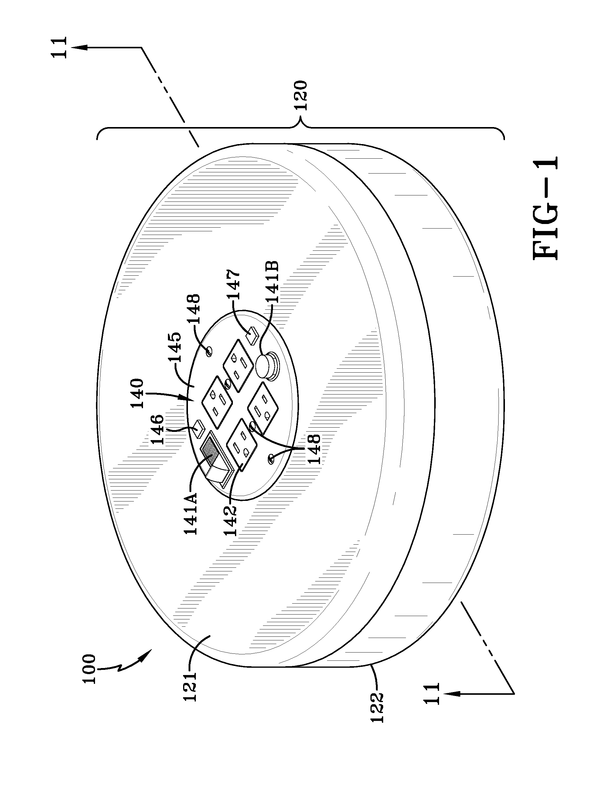
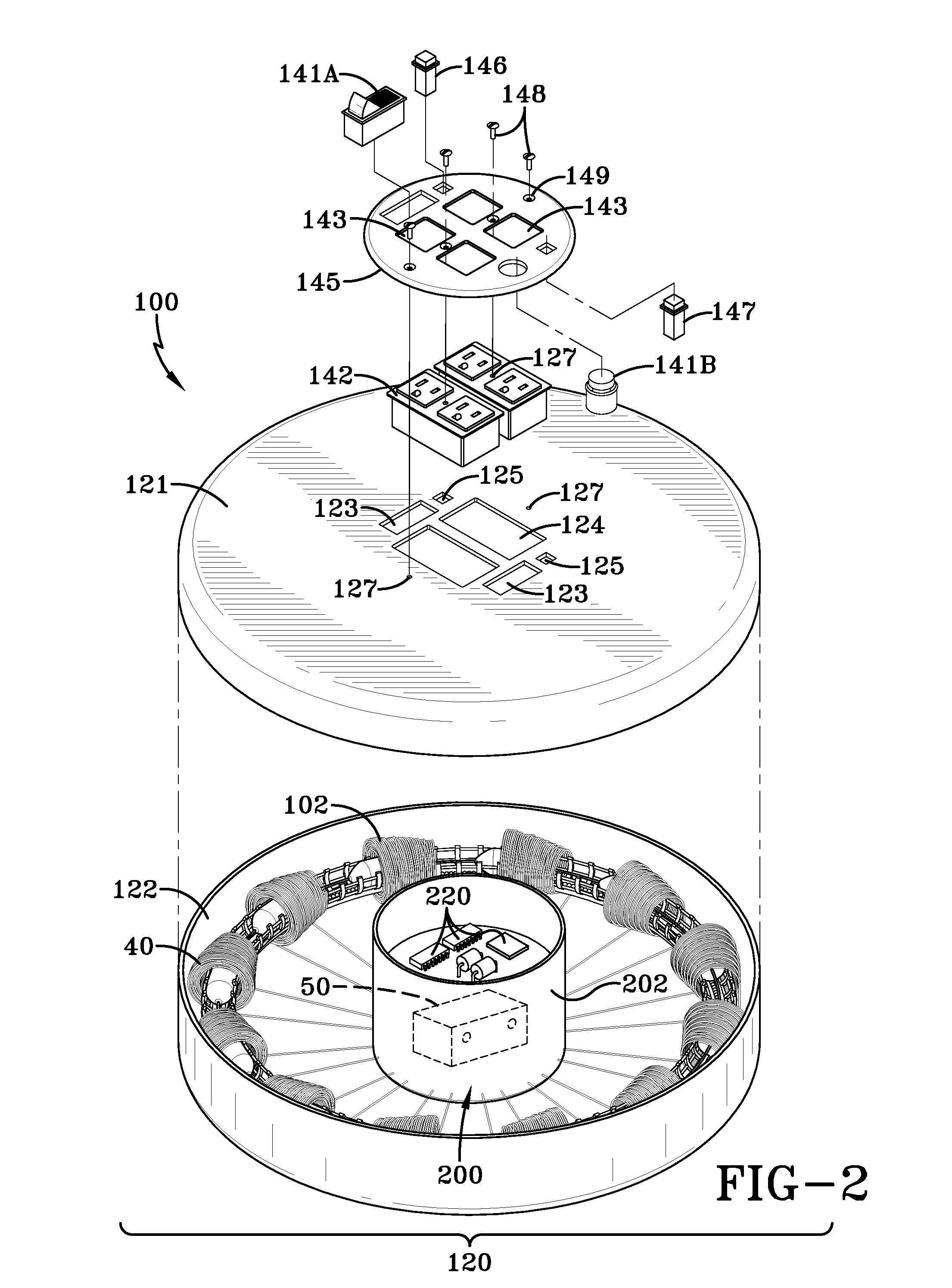
[0041]A geomagnetic power generator apparatus 100 of an exemplary first embodiment of the invention is illustrated in FIGS. 1-15B. As shown in FIG. 1, the generator apparatus 100 has an external housing 120 made...


PUM


Abstract

A geomagnetic power generating apparatus 100 has a guide means 20, one or more moving permanent magnets 10, a plurality of coils 40 and a battery 50 or series of batteries. The one or more moving permanent magnets 10, each permanent magnet 10 has a north polarity N at a first end 11 and a south polarity S at the opposite second end 12. The one or more magnets 10 are located and guided along a guide path GP by the guide means 20. The plurality of coils 40 has each coil 40 positioned around the guide means 20, encircling both the guide means 20 and the guide path GP along which one or more permanent magnets 10 move. Each coil 40 has a cross section having an increasing number of windings extending from a minimal winding first end 44 to a maximum winding second end 45. The battery 50 or a series of batteries is connected to the plurality of coils 40. When the one or more permanent magnets 10 are moved, with one magnet 10 approaching toward each coil 40 and as the N or S end of the magnet 10 approaches inside the coil 40 an electric current is created along with a magnetic field having an opposite polarity at the narrow end 44 of the coil 40 relative to the entering end of the magnet 10. As the movement of the one or more permanent magnets 10 generates an electric current in the coils 40 to charge the battery 50 and as the magnet 10 leaves the thick end 45 of the coil 40 a similar or like pole S to S or N to N polarity exists causing the magnetic field of each of the coils 40 to push the similar polarity second end 12 of the magnet 10 out of the coil 40, propelling the magnet 10 to the next coil 40. The moving magnets 10 generate electric currents within the coils 40 causing a major propulsive magnetic field to act on the magnet 10 augmenting its momentum along the guide path GP.

Description

TECHNICAL FIELD[0001]The present invention relates to an apparatus that generates electric currents through a plurality of coils to power or charge a battery using one or more moving permanent magnets passing through coils. This power generation is sustained by the persistence of magnetism in the permanent magnets for long periods, perhaps indefinitely. This persistence of magnetism, we contend is because the magnets are constantly being re-magnetized by proximity to the magnetic field of the earth (Geomagnetism). The movement of the magnet(s) is maintained by strategic design and deployment of the coils which themselves act as “air coils” and thus drive the magnets by repulsion of like magnetic poles. In this, momentum imparted by mass and velocity, in conjunction with gravity, function in a complimentary fashion. It will be clear to everyone that in this invention, electric power is generated simply by converting magnetic fluxes through known principles, but with special design fe...

Claims


Application Information

Patent Timeline
IPC IPC(8): H02K7/18H02N11/00
CPCH02K53/00
Inventor RAGHUPRASAD, PUTHALATH KOROTH
Owner RAGHUPRASAD PUTHALATH KOROTH
Why Eureka
Try Eureka