A thermodynamic machine

a thermodynamic machine and heat pump technology, applied in the direction of machines/engines, efficient propulsion technologies, mechanical apparatuses, etc., can solve the problems of low efficiency, large energy consumption for domestic and industrial heating and cooling, and low efficiency of effective pumping of working fluid by non-mechanical means, so as to reduce heat transfer

Active Publication Date: 2016-04-14
XEICLE
View PDF4 Cites 17 Cited by
  • Summary
  • Abstract
  • Description
  • Claims
  • Application Information

AI Technical Summary

Benefits of technology

[0116]Preferably the casing is at least partially thermally insulated

Problems solved by technology

However in the case of absorption heat pumps changes in temperature of absorption liquids or solids are used to cyclically absorb a working fluid at lower pressure and then release it at a higher pressure thereby effectively pumping the working fluid by non-mechanical means but with typically low efficiency.
Similarly Vuilleumier cycle heat pumps utilise a high temperature input of heat energy to drive a heat pumping cycle between a cold heat source and warm heat sink, but have not been widely used due to difficulties with economic implementation.
Much energy consumption is for domestic and industrial heating and cooling.
Electricity is a common medium by which this power is distributed and is typically a high cost source of energy due to generation and distribution costs that frequently make it several times the cost of an equivalent quantity of heat energy available to them from other sources such as geothermal heat, natural gas, other combustible fuels, solar, nuclear or waste heat sources.
Waste heat streams in the form of hot fluids like engine exhausts, cooling fluids and other hot industrial fluids are frequently large in size but uneconomic to exploit, with man

Method used


Image

  • A thermodynamic machine
  • A thermodynamic machine
  • A thermodynamic machine

Examples


Embodiment Construction

[0254]The invention will now be described in general terms before expanding upon various areas and features in more detail.

Description of Rotor Compression and Expansion Processes

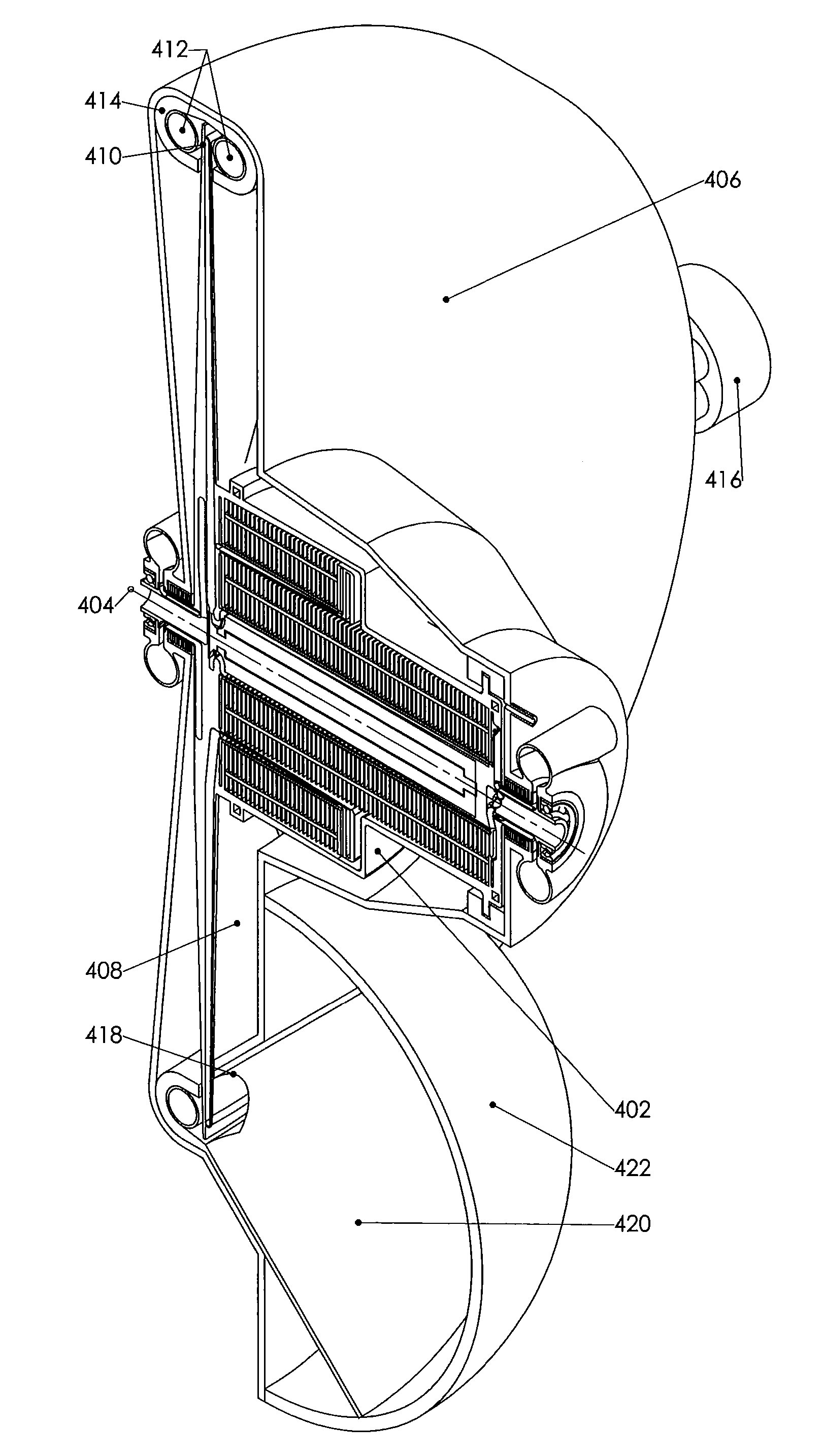
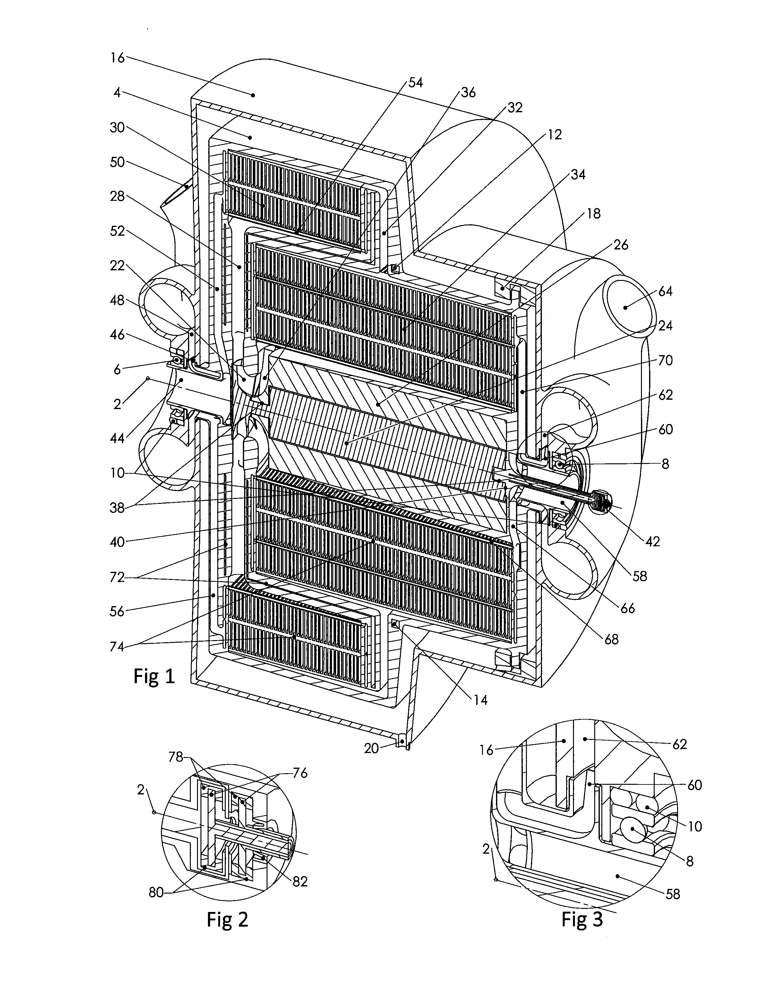
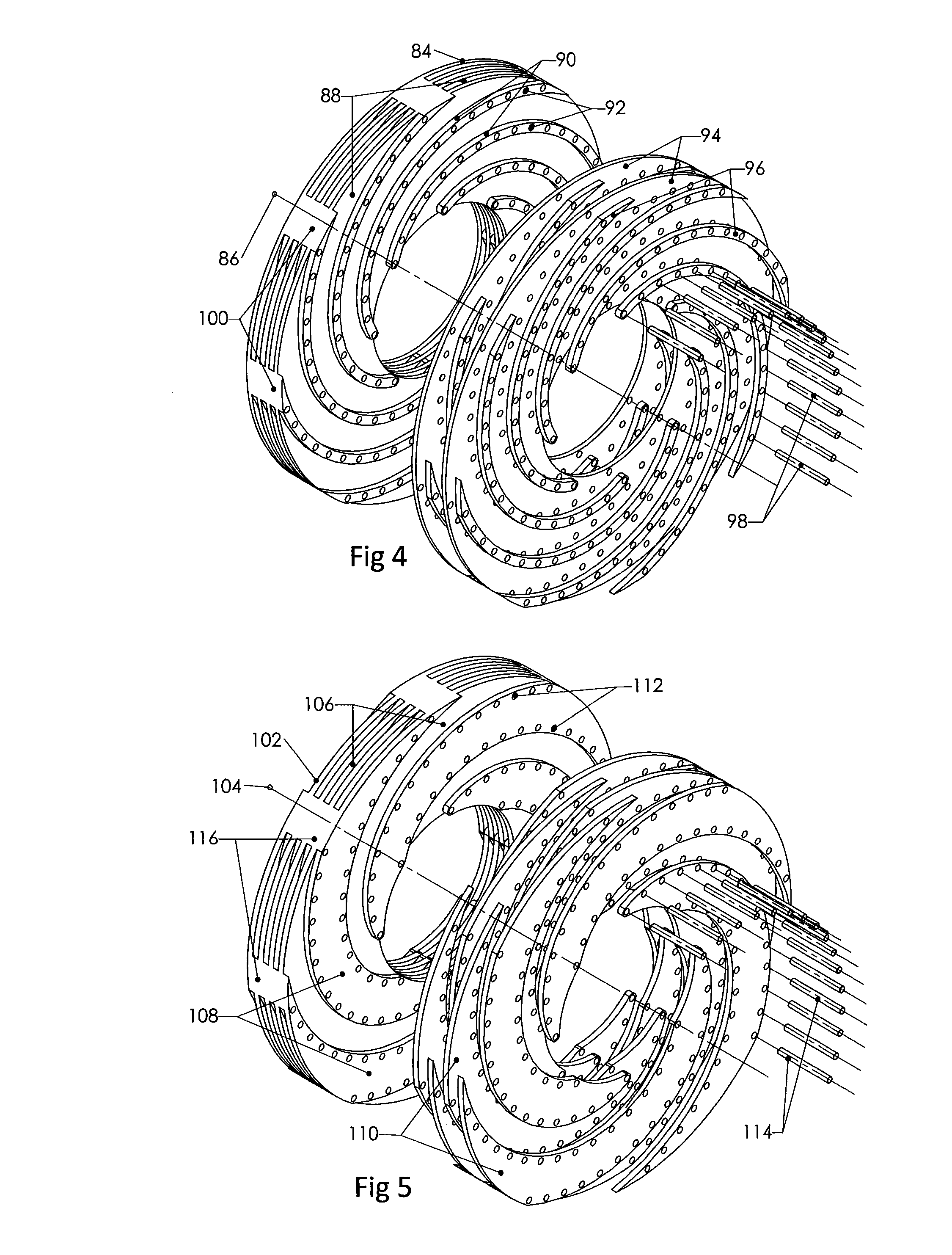
[0255]The heat pumps and engines of the current invention utilise a rotor that rotates about a rotor axis. A gaseous working fluid is circulated at typically relatively low flow speeds around a generally hermetically sealed working fluid circulation path within the rotor that takes it from near the rotor axis, to near the periphery of the rotor and back. This working fluid is subjected to large centripetal accelerations within the spinning rotor that result in radial pressure gradients due to the action of the acceleration on the working fluid mass. As the working fluid circulates around the working fluid circulation path within the rotor the centripetal accelerations result in high efficiency compression as the fluid travels away from rotor axis and high efficiency expansion as the fluid travels towards th...


PUM


Abstract

A thermodynamic machine, comprising: a rotor, configured to rotate about a rotor axis, a working fluid circulation path and a coolant fluid path formed within the rotor, the coolant fluid path fluidically isolated from the working fluid circulation path, the working fluid circulation path spanning radially from the rotor axis to close to the periphery of the rotor; a working fluid circulation drive configured to drive the circulation of a working fluid about the working fluid circulation path; at least one working fluid cooler heat exchanger formed as part of the working fluid circulation path and the coolant fluid path, in use coolant fluid passing through the working fluid cooler heat exchanger to transfer heat from the working fluid to the coolant fluid, and; a working fluid heater in the working fluid circulation path configured to heat a working fluid circulating around the working fluid circulation path.

Description

FIELD OF THE INVENTION[0001]The present invention relates to a thermodynamic machine. More particularly, the invention relates to a closed cycle heat pump or engine having a rotor that rotates and contains rare or noble gases as the working fluid that are sealed within the rotor and undergo cyclical thermodynamic processes. Even more particularly the rotor in some configurations rotates within a sealed and evacuated casing with ports at one or both ends of the rotor to allow cooling and heating fluids to enter and exit the rotor through rotor fluid ports, and in some configurations through rotary vacuum seals that seal the fluids from the evacuated casing. Even more particularly, the invention relates to a closed cycle heat pump or engine with compact radial spiral heat exchangers. Even more particularly, the invention relates to a closed cycle heat pump or engine where external liquids (coolant fluid and heating fluid / s) are passed to and from the rotor at opposite ends of rotor to...

Claims


Application Information

Patent Timeline
IPC IPC(8): F02G1/055
CPCF02G1/055F01K11/04F01K25/00F02C1/10Y02T50/60
Inventor LYNN, ROBERT GULLIVER
Owner XEICLE
Why Eureka
Try Eureka