Connector assembly having locking members

a technology of locking member and connector assembly, which is applied in the direction of coupling device connection, coupling parts engagement/disengagement, electrical apparatus, etc., and can solve problems such as undesirable consequences

Active Publication Date: 2016-03-08
TYCO ELECTRONICS BRASIL
View PDF5 Cites 46 Cited by
  • Summary
  • Abstract
  • Description
  • Claims
  • Application Information

AI Technical Summary

Benefits of technology

[0006]An embodiment is directed to a connector assembly including a cover with a locking member receiving portion and a latch retaining portion. A latch, positioned in the latch retaining portion when the latch is in the latched position, is movable between an unlatched position and a latched position. A locking member is movably retained in the locking member receiving portion and is moveable between an unlocked position and a locked position. A portion of the locking member is positioned in the latch retaining portion when the locking member is in the locked position. The locking member engages the latch when the locking member is in the locked position to properly secure the latch in the latched position and to ensure continuous latching of the connector assembly.
[0007]An embodiment is directed to a connector assembly including a cover with a locking member receiving portion and a latch retaining portion. A latch, positioned in the latch retaining portion when the latch is in the latched position, is movable between an unlatched position and a latched position. A locking member is movably retained in the locking member receiving portion and is moveable between an unlocked position and a locked position. The locking member includes a retention member and a latch engagement portion. The retention member engages the latch when the locking member is in the locked position. The lever engagement portion is positioned proximate to the retention member and cooperates with the latch as the latch is moved from the unlatched position to the latched position. The retention member engages the latch when the locking member is in the locked position to properly secure the latch in the latched position and to ensure continuous latching of the connector assembly.

Problems solved by technology

For example, in automotive applications wherein electrical signals are routed to safety equipment such as air bag deployment systems or other systems relating to the operational or safety features of the vehicle, disconnection of the electrical signals as a result of accident, operating conditions such as vibration, etc. may result in undesirable consequences.

Method used


Image

  • Connector assembly having locking members
  • Connector assembly having locking members
  • Connector assembly having locking members

Examples


Embodiment Construction

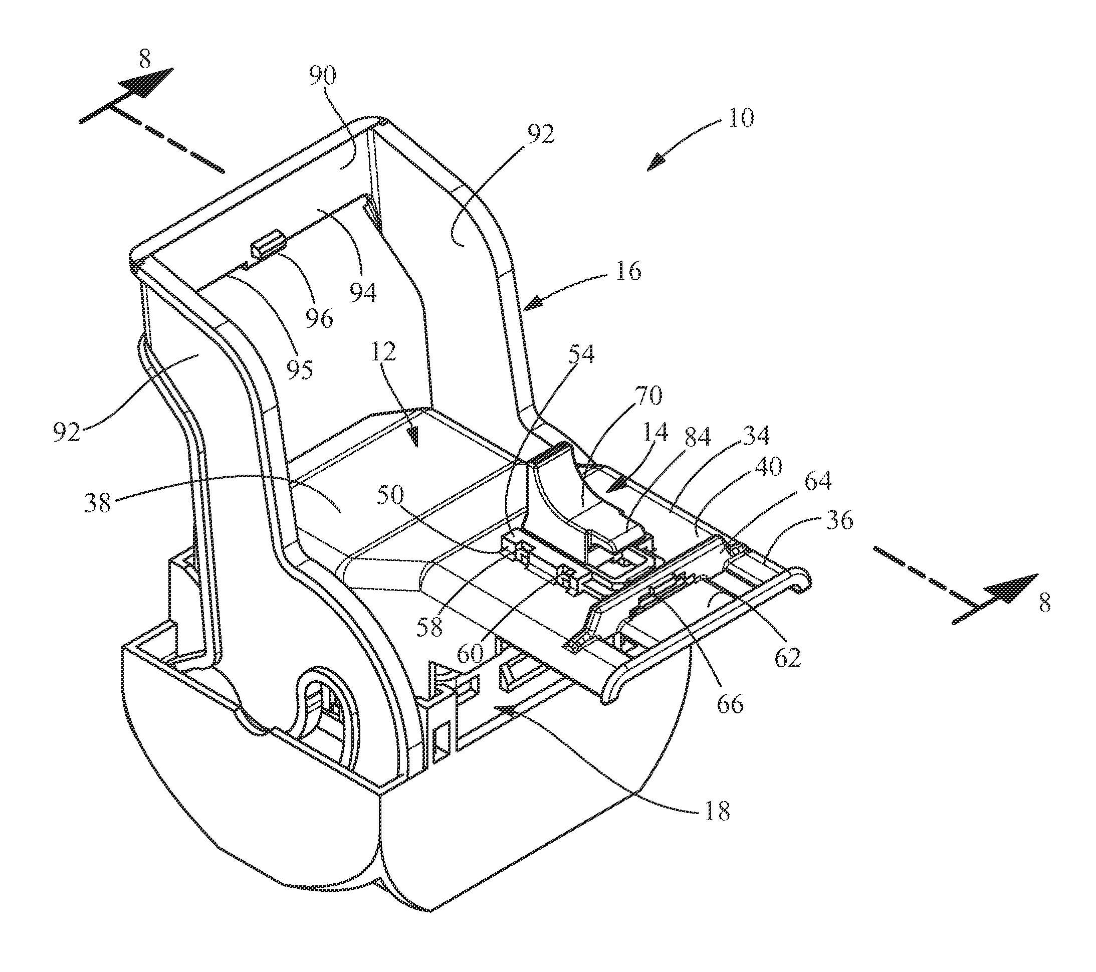
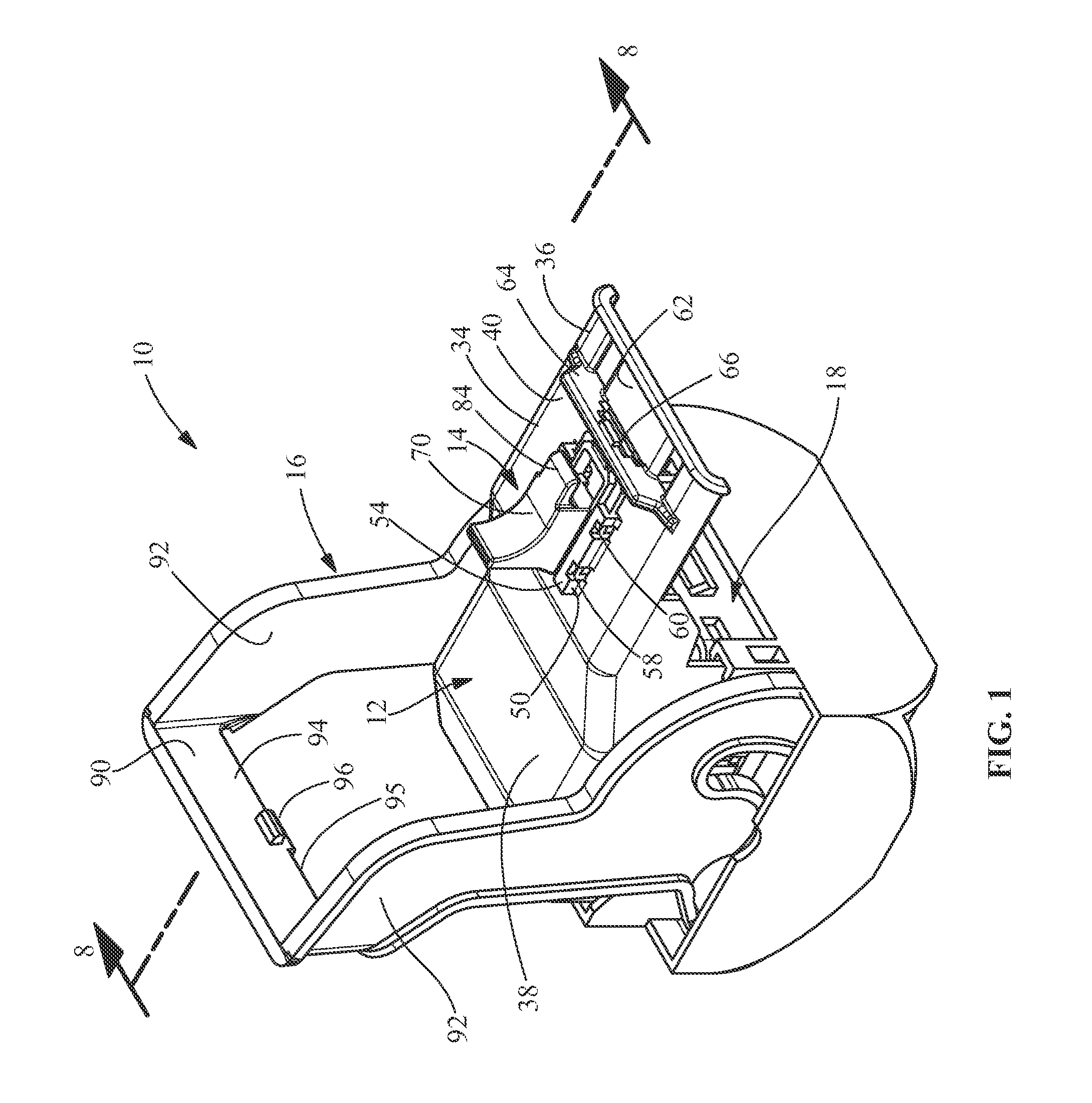
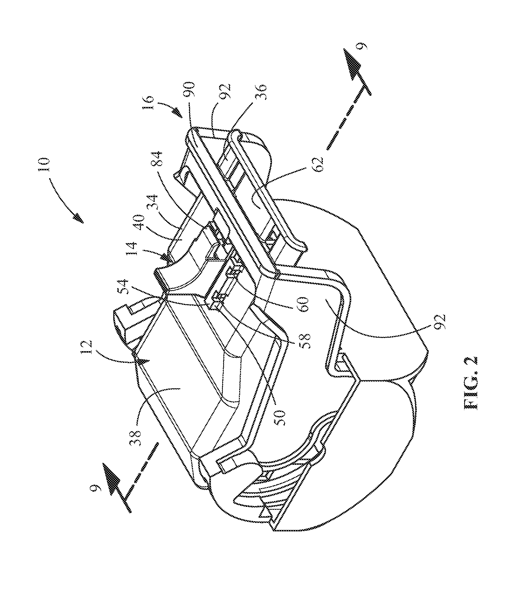
[0020]The present invention will be described more fully hereinafter with reference to the accompanying drawings, in which illustrative embodiments of the invention are shown. In the drawings, the relative sizes of regions or features may be exaggerated for clarity. This invention may, however, be embodied in many different forms and should not be construed as limited to the embodiments set forth herein; rather, these embodiments are provided so that this disclosure will be thorough and complete, and will fully convey the scope of the invention to those skilled in the art.

[0021]It will be understood that spatially relative terms, such as “top”, “upper”, “lower” and the like, may be used herein for ease of description to describe one element's or feature's relationship to another element(s) or feature(s) as illustrated in the figures. It will be understood that the spatially relative terms are intended to encompass different orientations of the device in use or operation in addition ...


PUM


Abstract

A connector assembly including a housing and a cover. The cover including a locking member receiving portion and a lever retaining portion. A lever rotatable between an unlatched position and a latched position is provided. The lever is positioned in the lever retaining portion when the lever is in the latched position. A locking member is movably retained in the locking member receiving portion. The locking member is moveable between an unlocked position and a locked position. A portion of the locking member is positioned in the lever retaining portion when the locking member is in the locked position. The locking member engages the lever when the locking member is in the locked position to properly secure the lever in the latched position and to ensure continuous latching of the connector assembly.

Description

FIELD OF THE INVENTION[0001]The present invention relates generally to electrical connectors, and more particularly to a locking member for a lever actuated connector.BACKGROUND OF THE INVENTION[0002]In certain applications, electrical connectors must be securely mated to one another to prevent disconnection of the electrical signals routed through the connector conductors. For example, in automotive applications wherein electrical signals are routed to safety equipment such as air bag deployment systems or other systems relating to the operational or safety features of the vehicle, disconnection of the electrical signals as a result of accident, operating conditions such as vibration, etc. may result in undesirable consequences. Thus, some electrical connectors are coupled to connector assemblies that mechanically lock the electrical connectors in mating engagement with one another.[0003]Some conventional connector assemblies include a housing that houses an electrical connector, a...

Claims


Application Information

Patent Timeline
Patent Type & Authority Patents(United States)
IPC IPC(8): H01R13/62H01R13/627
CPCH01R13/6272H01R13/62927H01R13/62938H01R13/62955
Inventor BONUCCI, GUSTAVOPULGROSSI, PETERSON
Owner TYCO ELECTRONICS BRASIL
Why Eureka
Try Eureka