Method for designing an acoustic array

Active Publication Date: 2016-03-15
UNITED STATES OF AMERICA
View PDF5 Cites 3 Cited by
  • Summary
  • Abstract
  • Description
  • Claims
  • Application Information

AI Technical Summary

Benefits of technology

[0011]Yet another object is to provide an acoustic array having a beam pattern that

Problems solved by technology

These methods teach suppression of sidelobes by area shading, but they don't teach

Method used


Image

  • Method for designing an acoustic array
  • Method for designing an acoustic array
  • Method for designing an acoustic array

Examples


Example

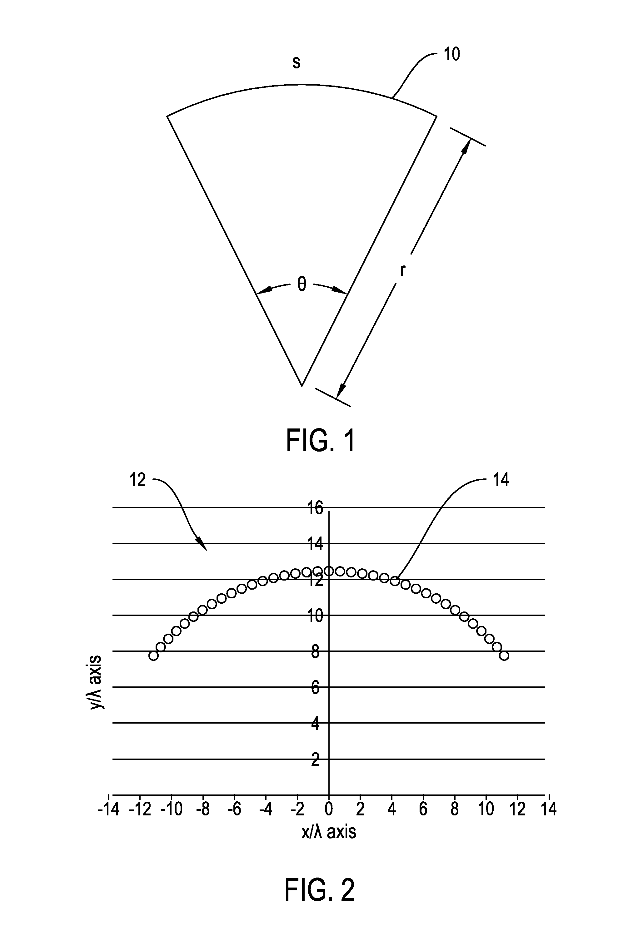
[0027]FIG. 1 shows a line source 10 curved circularly. This type of source produces a constant wide beam pattern over a broad frequency band. The beamwidth (BW) of the pattern is controlled by the active area arc length s and angle (θ) coverage when the aperture radius r is much greater than the acoustic wavelength λ. The −6 dB beamwidth (BW −6 dB) is approximately equal to the total angle (θ) in degrees when r>8λ. The beamwidth in degrees of a lobe is ordinarily measured from where the signal falls off by 6 dB on either side of the main lobe. As known in the art, this is the −6 dB beamwidth. In source 10, the −6 dB beamwidth (BW −6 dB) is approximately equal to the angle (θ) of the source 10 in degrees when r>8λ.

[0028]FIG. 2 shows this line source modeled as an array 12 of discrete point sources 14 along an arc. This array 12 has one point source 14 at every degree from +55° to −55° (110° total and 111 point sources) and a radius of 13.75 wavelengths (r=13.75λ). In FIG. 2, the x-y ...


PUM


Abstract

A method for designing an acoustic array includes establishing a desired beam pattern, acoustic wavelength and beamwidth for the array. Geometric parameters are calculated from these constraints. The array is modeled as a plurality of elements positioned in accordance with the geometric parameters. An amplitude shading function is calculated. An array of acoustic elements is constructed having an area calculated from the calculated amplitude shading function. An acoustic array designed by this process is further provided.

Description

STATEMENT OF GOVERNMENT INTEREST[0001]The invention described herein may be manufactured and used by or for the Government of the United States of America for governmental purposes without the payment of any royalties thereon or therefor.CROSS REFERENCE TO OTHER PATENT APPLICATIONS[0002]None.BACKGROUND OF THE INVENTION[0003](1) Field of the Invention[0004]The present invention is directed to a method for designing an acoustic array and more particularly to a method for designing an acoustic array with simplified wiring and processing.[0005](2) Description of the Prior Art[0006]Beamforming is used in active and passive sonar to increase the efficiency or gain from an array of transducers. In such an array, each transducer is separately wired to acoustic processing equipment. The acoustic processing equipment adjusts the power and time delay associated with the joined transducer. This requires separately controlling the signal associated with each array element.[0007]Conventional arra...

Claims


Application Information

Patent Timeline
IPC IPC(8): G10K11/32G06F17/50G10K11/34
CPCG06F17/50G10K11/34G10K11/32G06F30/00G06F2119/10
Inventor BUTLER, STEPHEN CFRANK, THOMAS ADIAPIS, JACKELINE D
Owner UNITED STATES OF AMERICA
Why Eureka
Try Eureka