Water treatment method and system providing partial dynamic by-pass of water treatment stages

Inactive Publication Date: 2017-10-26
LOCALIZED WATER SOLUTIONS LLC
View PDF6 Cites 3 Cited by
  • Summary
  • Abstract
  • Description
  • Claims
  • Application Information

AI Technical Summary

Benefits of technology

[0005]Embodiments of the present invention are directed to water treatment systems and methods offering improved efficiency, longevity and versatility. More specifically, water treatment systems and methods configured in accordance with the present invention provide for dynamic bypass of one or more water treatment stages by at least a portion of water being treated. Dynamic bypass reduces the amount of work expended by water t

Problems solved by technology

Furthermore, partial bypass where some water is treated to a different degree than other and then recombined is conjectured to not exist

Method used


Image

  • Water treatment method and system providing partial dynamic by-pass of water treatment stages
  • Water treatment method and system providing partial dynamic by-pass of water treatment stages
  • Water treatment method and system providing partial dynamic by-pass of water treatment stages

Examples


Example

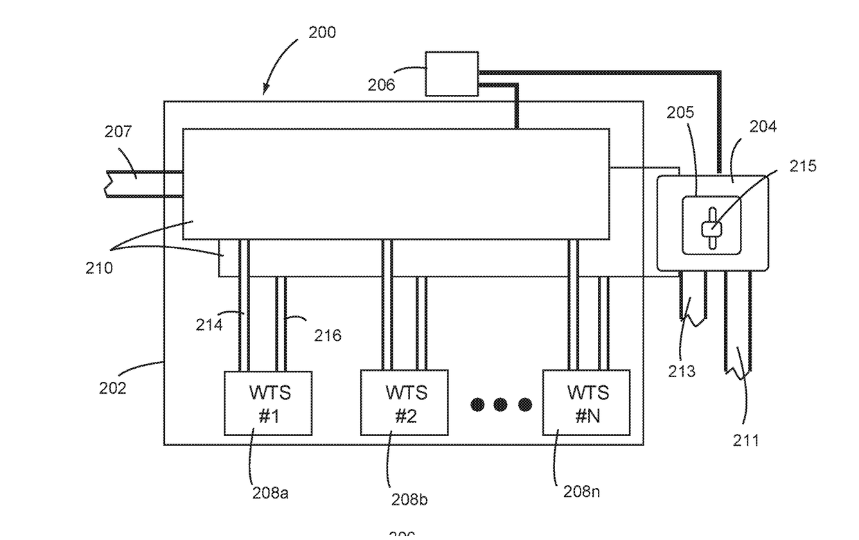
[0029]FIG. 5 shows first embodiment of a water treatment system configured in accordance with the present invention (water treatment system 200). The water treatment system 200 includes a water treatment apparatus 202, a water discharge structure 204, and a water treatment controller 206. The water treatment apparatus 202 includes a plurality of water treatment stages 208a-208n interconnected by a flow control structure 210. The water discharge structure 204 is coupled to the water treatment apparatus 202 for receiving water from the flow control structure 210. The water treatment controller 206 is coupled to the flow control structure 210 for providing control information (e.g., signals) thereto and is coupled to a water quality determining apparatus 205 of the water discharge structure 204 for receiving treated water quality information (e.g., water quality sensor output signal(s)) therefrom.

[0030]The water discharge structure 204 and the flow control structure 210 are jointly con...

Example

[0037]FIG. 6 shows second embodiment of a water treatment system configured in accordance with the present invention (water treatment system 300). The water treatment system 300 includes a water treatment apparatus 302, a water discharge structure 304, and a water treatment controller 306. The water treatment apparatus 302 includes a plurality of water treatment stages 308a-308n interconnected by a flow control structure 310. The water discharge structure 304 is coupled to the water treatment apparatus 302 for receiving water from the flow control structure 310 The water treatment controller 306 is coupled to the flow control structure 310 for providing control information (e.g., signals) thereto and is coupled to a water quality determining apparatus 305 of the water discharge structure 304 for receiving treated water quality information (e.g., water quality sensor output signal(s)) therefrom. The water treatment system 300 functions generally similar to the water treatment system ...


PUM


Abstract

Embodiments of the present invention are directed to water treatment systems and methods offering improved efficiency, longevity and versatility. More specifically, water treatment systems and methods configured in accordance with the present invention provide for dynamic bypass of one or more water treatment stages by at least a portion of water being treated. Dynamic bypass reduces the amount of work expended by water treatment system components to treat a given volume of water. Thus, by adjusting such work expended based on a target water quality, the water treatment system can conserve power, extend system up-time, reduce usage of system consumables, potentially remediate a fault in a treatment stage under certain conditions, avoid the need for designing different systems for different conditions, and support automation of system operation.

Description

FIELD OF THE DISCLOSURE[0001]The disclosures made herein relate generally to water treatment methods and systems and, more particularly, to water treatment methods and systems configured for providing partial dynamic by-pass of water treatment stages.BACKGROUND[0002]In various industries and applications, there is often a need for treated water meeting suitable water quality criteria for consumption and / or industrial use. However, available sources of water can suffer from any number of water quality considerations that can preclude its use for human consumption and / or industrial use. Examples of such water quality considerations include, but are not limited to, bulk contaminants (e.g., biological matter such as plant matter), mineral inclusion (e.g., salt), presencet of microorganisms (e.g., bacteria, virus, cysts, protozoa, and the like), etc.[0003]Remote locations represent a particular situation in which water having a suitable quality for human consumption and / or industrial use...

Claims


Application Information

Patent Timeline
IPC IPC(8): C02F1/00G05D7/06
CPCC02F1/008G05D7/0635C02F2301/043C02F2209/006C02F2303/04C02F1/283C02F1/32C02F1/441C02F1/444C02F1/78C02F2209/05C02F2209/40G05D7/0623
Inventor BRAUN, URILAMY, JOSEPH SAUGRAIN
Owner LOCALIZED WATER SOLUTIONS LLC
Why Eureka
Try Eureka