
Apparatus for power line communication

a power line communication and apparatus technology, applied in the direction of power distribution line transmission, digital transmission, transmission path division, etc., can solve the problems of power line communication signal magnitude exceeding the reference value allowed in the law, and the communication performance of the modem deterioration, etc., to achieve the effect of low output communication signal magnitud

Active Publication Date: 2016-03-15
LSIS CO LTD
View PDF8 Cites 16 Cited by
  • Summary
  • Abstract
  • Description
  • Claims
  • Application Information

AI Technical Summary

Benefits of technology

The patent describes an apparatus for power line communication that controls the output of a communication signal to be low in magnitude, to reduce distortion and malfunctions. The apparatus automatically distinguishes each phase of the three-phase power line, stores information about the phase of the communication target device, and controls the opening / closing of a switch connected to each phase. This makes the apparatus operable like a single-phase apparatus, reduces power consumption, and makes maintenance, replacement, and examination of devices, communication lines, and power lines easier. The technical effects of this invention are improved stability and flexibility in power line communication.

Problems solved by technology

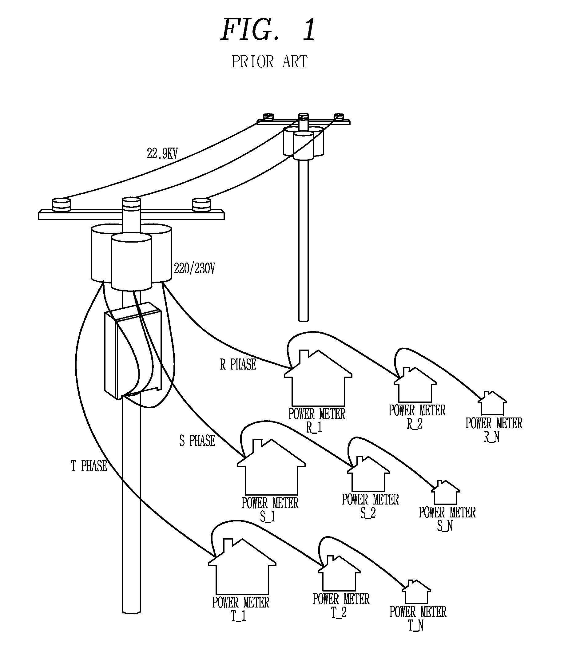
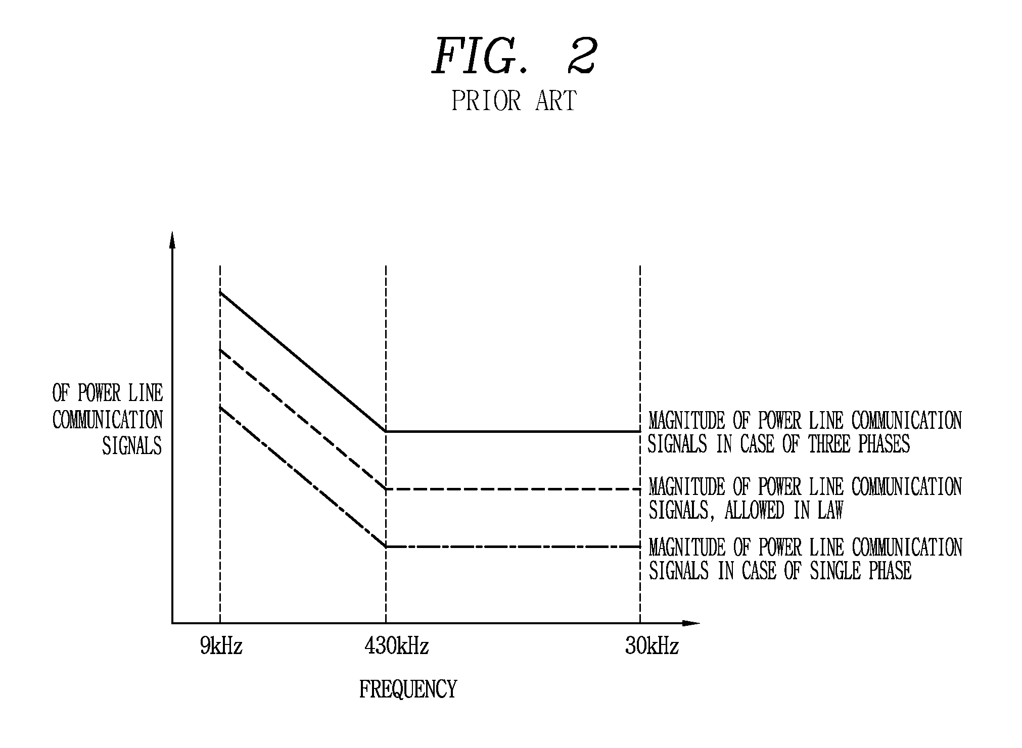
If the modem designed based on the single phase is applied to the three phases without any correction, the output driving performance of the analog processor is insufficient, and therefore, the communication performance of the modem is deteriorated.
In order to prevent the deterioration of the communication performance, if the output of the analog processor is designed to be three times greater than that based on the single phase, the communication performance is improved, but the magnitude of power line communication signals exceeds the reference value allowed in the law. FIG. 2 shows a problem in that, in the case of three-phases, the magnitude of power line communication signals exceeds the reference value allowed in the law.

Method used


Image

  • Apparatus for power line communication
  • Apparatus for power line communication
  • Apparatus for power line communication

Examples


Embodiment Construction

[0034]Description will now be given in detail of the exemplary embodiments, with reference to the accompanying drawings. For the sake of brief description with reference to the drawings, the same or equivalent components will be provided with the same reference numbers, and description thereof will not be repeated.

[0035]The present disclosure may be applied to an apparatus for power line communication. However, the present disclosure is not limited thereto, and may be applied to all existing apparatus and systems for power line communication to which the technical spirit of the present disclosure is applicable. Particularly, the present disclosure can be applied and embodied in remote metering through power line communication.

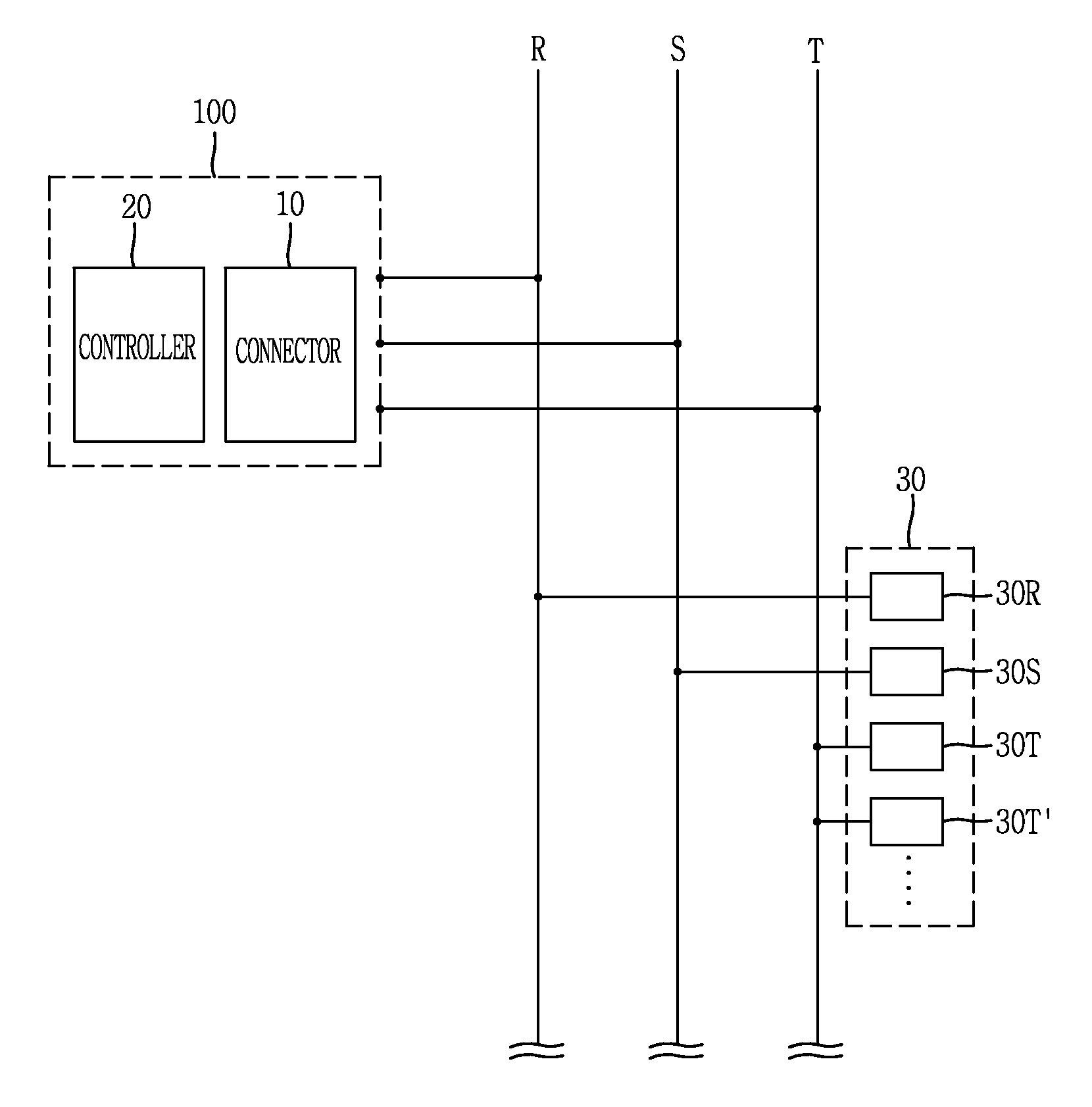
[0036]First, the configuration of an apparatus for power line communication according to the present disclosure will be described with reference to FIG. 3.

[0037]FIG. 3 is a configuration view an apparatus for power line communication according to the present di...


PUM


Abstract

Disclosed is an apparatus for power line communication. More specifically, in order to solve a problem of the conventional art, in which the magnitude of power line communication signals exceeds a reference value allowed in the law, the apparatus controls a communication signal to be selectively output a communication target phase among phases of a three-phase power line. Accordingly, it is possible to maintain the magnitude of the output communication signal to be low. Further, it is possible to reduce distortion of a power signal, caused by the communication signal, and malfunction of other power facilities due to the distortion. Further it is possible to easily and simply perform initiation of the power line communication.

Description

CROSS-REFERENCE TO RELATED APPLICATIONS[0001]Pursuant to 35 U.S.C. §119(a), this application claims the benefit of earlier filing date and right of priority to Korean Application No. 10-2013-0159524, filed on Dec. 19, 2013, the contents of which is incorporated by reference herein in its entirety.BACKGROUND OF THE DISCLOSURE[0002]1. Field of the Disclosure[0003]The present disclosure relates to an apparatus for power line communication, and particularly, to an apparatus for power line communication, in which a communication signal is selectively output to a communication target phase among phases of a three-phase power line.[0004]2. Description of the Background Art[0005]Power line communication has advantages of low investment costs in view of using existing power lines without installation of another communication line, and simplified communication by connecting a plug into a socket installed on a wall. Therefore, the power line communication is considered as the most appropriate ...

Claims


Application Information

Patent Timeline
Patent Type & Authority Patents(United States)
IPC IPC(8): H04B3/54H04L5/00H04B3/56
CPCH04B3/542H04B3/56H04L5/0005H04B2203/542H04B2203/5466H04B2203/5483
Inventor YU, YOUNG, GYU
Owner LSIS CO LTD
Learn More