Heated disposable gloves

Active Publication Date: 2016-03-29
DEOLA III PAUL
View PDF12 Cites 7 Cited by
  • Summary
  • Abstract
  • Description
  • Claims
  • Application Information

AI Technical Summary

Benefits of technology

[0008]It is another object of the present invention to provide a

Problems solved by technology

A quantity of exothermic chemicals is sealed within each of the pouches whereby removing chemic

Method used


Image

  • Heated disposable gloves
  • Heated disposable gloves
  • Heated disposable gloves

Examples


Embodiment Construction

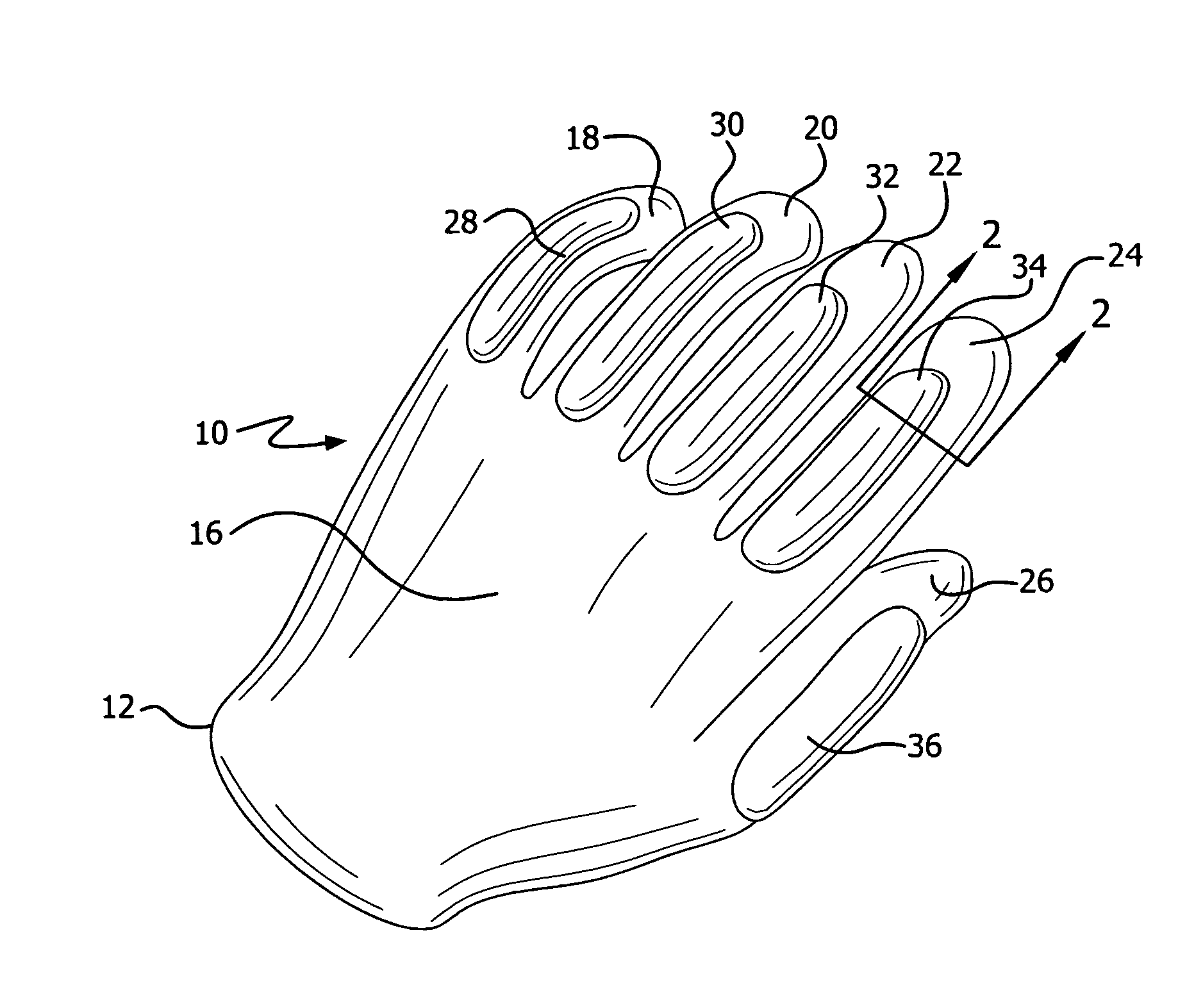
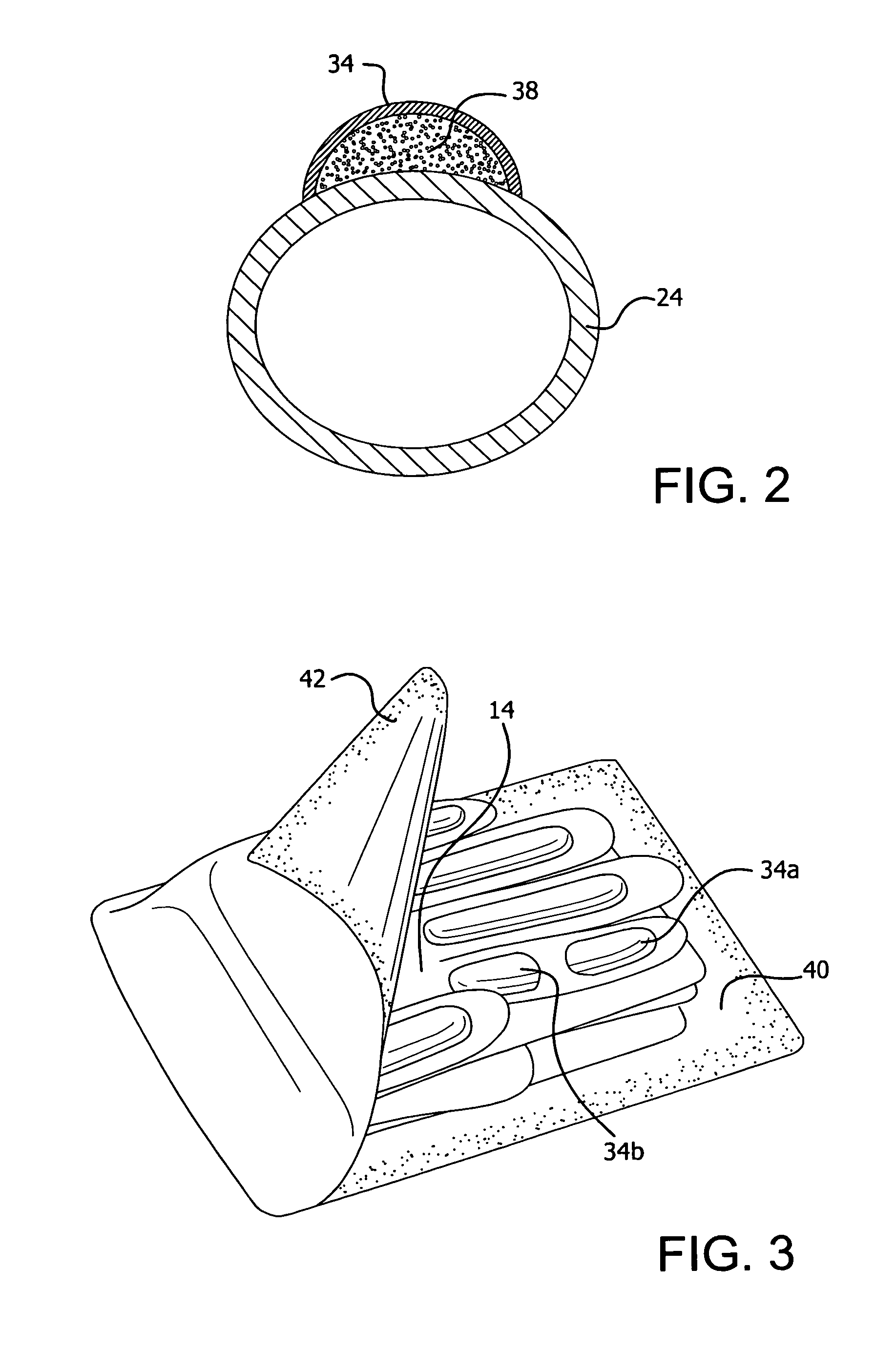
[0016]Referring now to the drawings in detail wherein like reference numerals have been used throughout the various figures to designate like elements, there is shown in FIG. 1 a disposable heated glove constructed in accordance with the principles of the present invention and designated generally as 10. The major portions of the glove 10 are constructed in a conventional manner well known in the art. It is made from a fabric material 12 that has a palm portion 14 (see FIG. 3) that is intended to cover the palm of a person's hand and a back portion 16 that is intended to cover the back of a person's hand.

[0017]There are also four finger portions 18, 20, 22 and 24 for covering the wearer's fingers and a thumb portion 26 for covering the wearer's thumb. Again, the glove thus far described is, per se, conventional in the art.

[0018]The material 12 from which the glove is made may be latex, polyvinyl chloride, polyurethane or any other plastics material. Alternatively, the glove could be...


PUM


Abstract

A disposable heated glove for heating a wearer's hand includes a fabric material for covering the palm and back of the hand, four finger portions for covering the wearer's fingers and a thumb portion for covering the wearer's thumb. The glove also includes five small elongated pouches with each pouch being associated with a different one of the finger and thumb portions. A quantity of exothermic chemicals is sealed within each of the pouches whereby removing chemicals from one of the pouches results in the destruction of the pouch so that it cannot be reused. In one embodiment, the chemicals are activated to create heat by manually manipulating the same to mix the chemicals. In another embodiment, the chemicals are activated by exposing them to the atmosphere.

Description

BACKGROUND OF THE INVENTION[0001]The present invention is directed toward heated gloves and more particularly, toward inexpensive gloves with chemical heaters integrally formed therewith and which are intended to be disposable after a single use.[0002]There are numerous times when it is necessary or simply desirable to wear heated gloves. Workers who must be outside on cold days, skiers or spectators at winter sporting events would benefit substantially from the same. Over the years, various types of heated groves have been proposed but to Applicant's knowledge none has been successful. This is probably due to the high cost of prior art gloves.[0003]Attempts to produce heated gloves have included electric heating elements within the gloves which requires a power source such as batteries carried by the gloves or on the person's body separate from the gloves. In either case, the batteries cannot last very long as electric heating elements draw a great deal of current and drain batteri...

Claims


Application Information

Patent Timeline
IPC IPC(8): A61F7/03F24J1/00F24V30/00
CPCA61F7/03A61F7/034F24J1/00A61F2007/0036A61F2007/0271A41D19/01535F24V30/00
Inventor DEOLA, JAMES, A.
Owner DEOLA III PAUL
Why Eureka
Try Eureka