Articulated Instrument with Simple Fabrication

a technology of articulation instruments and fabrication methods, applied in the field of articulation instruments with simple fabrication, can solve the problems of inability to maneuver instruments using instrument articulations, inconvenient control of multiple degrees of freedom, and inability to achieve straight-line access to the surgical site, etc., to achieve the effect of reducing cost and complexity

Pending Publication Date: 2022-10-13
NUTECH VENTURES
View PDF0 Cites 0 Cited by
  • Summary
  • Abstract
  • Description
  • Claims
  • Application Information

AI Technical Summary

Benefits of technology

[0011]In one exemplary but non-limiting aspect, the present disclosure describes a manual laparoscopic instrument with distributed degrees of freedom that further reduces cost and complexity by adopting a kirigami-based design. A scheme for direct manual control by the surgeon, which allows motion scaling, is also described.

Problems solved by technology

However, aggregating multiple degrees of freedom at a control point carries disadvantages.
One limitation of most of these devices (both manual and robotic instruments) is that straight-line access to the surgical site tends to be required, and the instrument articulations cannot be used to maneuver the instrument around obstacles that may be located along this straight line.
This is largely due to the difficulty of designing input mapping mechanisms for the user to control such an instrument, and consequently the solutions seen in the literature which use this approach are robotic.
(This does not consider backbone-type instruments, whose articulations are distributed along the continuum of the instrument but provide relatively little overall mobility in terms of effective degrees of freedom).
Although surgical robots can extend capabilities by enhancing dexterity compared to manual surgical instruments, one of the barriers to their use is cost.

Method used


Image

  • Articulated Instrument with Simple Fabrication
  • Articulated Instrument with Simple Fabrication
  • Articulated Instrument with Simple Fabrication

Examples


Embodiment Construction

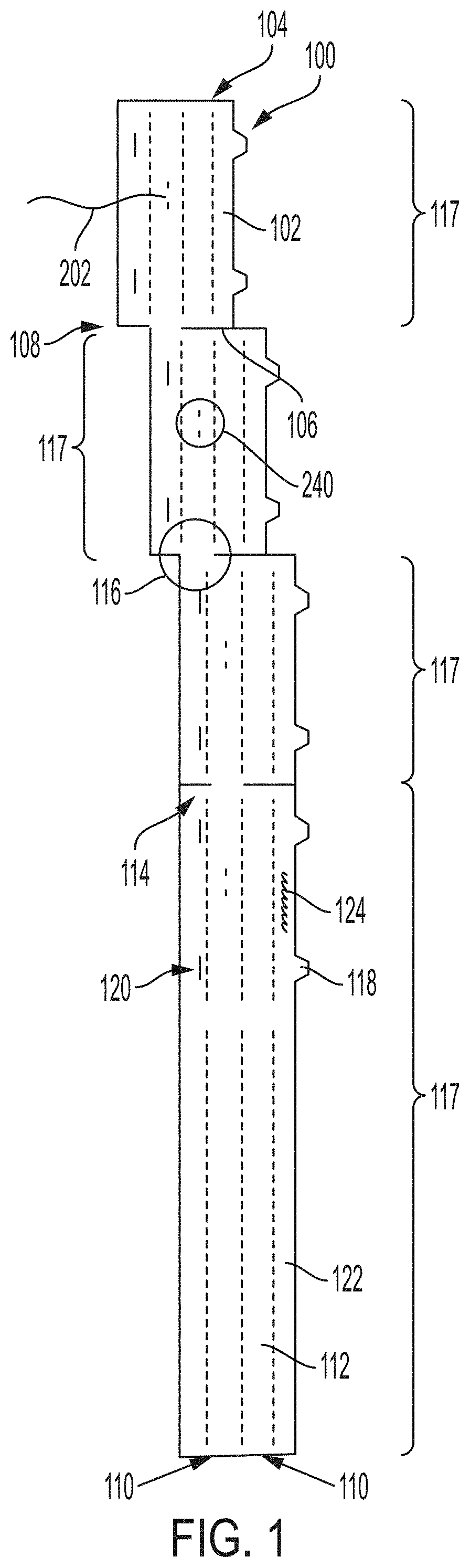
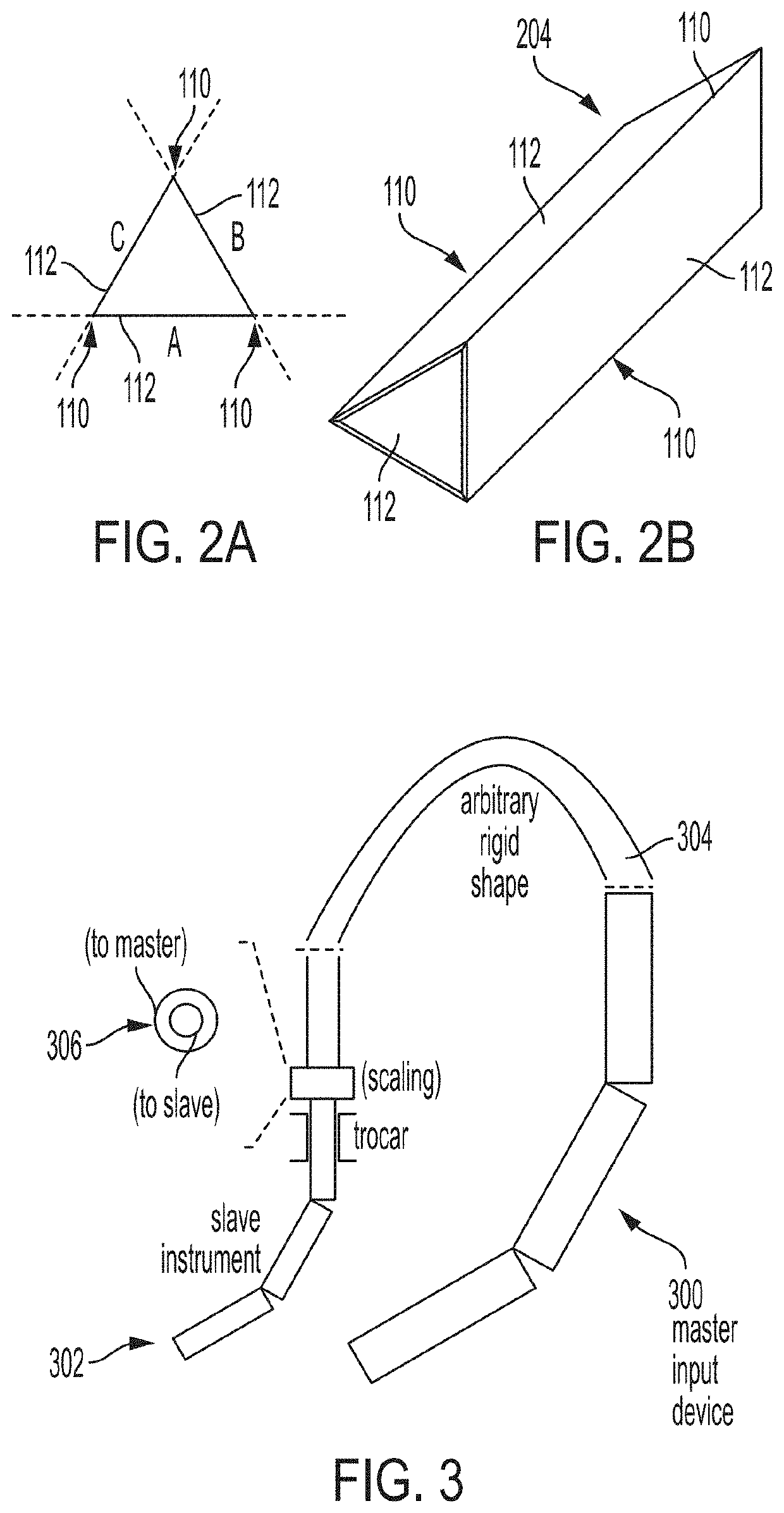
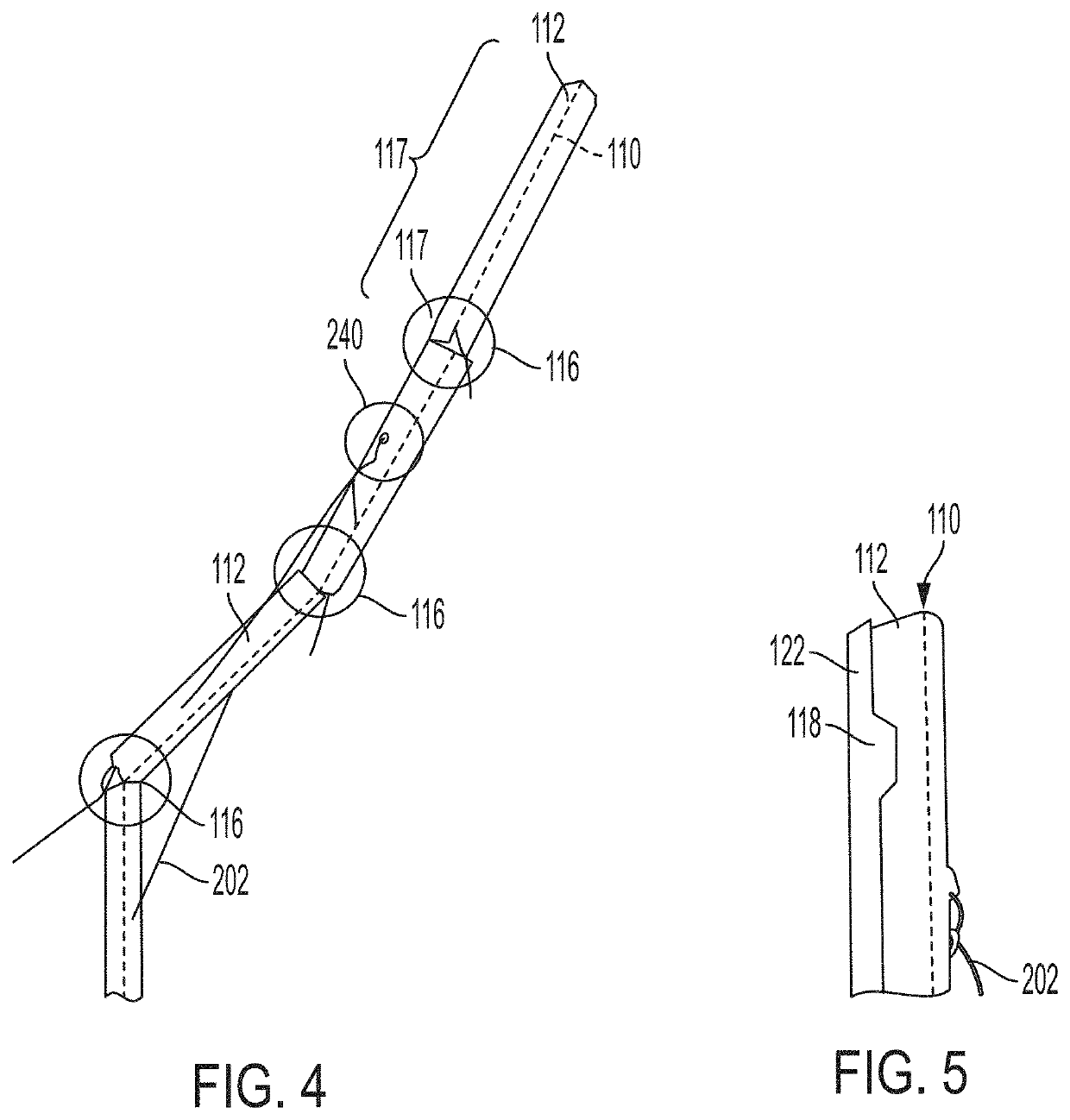
[0020]The present disclosure is directed to articulated instruments, their manufacture, and methods for their use. The systems and methods in accordance with the disclosure are consistent with and, in important respects, build upon previously proposed systems and methods. The articulated instruments in accordance with the present disclosure include an articulated serial kinematic chain of linkages, which provide distributed DOFs. The links are motively connected to one another in series and their individual motion is tendon-driven. The materials used to fabricate the articulated surgical instruments in accordance with the disclosure are relatively inexpensive and easy to fabricate. These materials utilize biocompatible materials and are compatible with standard trocars so they can be mounted for use and directly controlled by the user. In the illustrated embodiment, which is exemplary and non-limiting, the articulated instruments are surgical instruments for use by surgeons conducti...


PUM


Abstract

An articulated instrument and method of its manufacture includes a plurality of segments connected to one another end-to-end, each having a hollow tubular shape defined by a wall, the wall comprising three or more rectangular panels connected along their respective edges at acute angles. A plurality of tendons extends at least partially through the plurality of segments and is configured to apply tension that selectively causes two adjacent segments from the plurality of tendons to bend relative to one another along a pivot joint disposed between the two adjacent segments. The plurality of segments is formed by staggered rectangular portions of a single sheet of stock material, each rectangular portion being folded to form the hollow tubular shape and connected to an adjacent rectangular portion by a tab, each tab defining a respective pivot joint.

Description

CROSS-REFERENCE TO RELATED APPLICATIONS[0001]The present application claims the benefit of U.S. Provisional Patent Application No. 63 / 174,172, filed on Apr. 13, 2021, which is incorporated herein by this reference in its entirety for all purposes.BACKGROUND OF THE INVENTION[0002]Various applications in the fields of medical procedures, manufacturing, laboratory processes, parts assembly, motion simulators, and the like use linkages that are manually or mechanically operated to isolate an environment in which the linkages are working from the surrounding environment. For example, certain laboratory or clean room operations require manipulation of objects in a sterile environment created within an enclosure. The manipulation of these objects is effected by a machine or a user operating outside of the enclosure through the use of a linkage that is disposed in the enclosure but controlled externally to the enclosure. Another example involves laparoscopic surgery and medical procedures, ...

Claims


Application Information

Patent Timeline
Patent Type & Authority Applications(United States)
IPC IPC(8): A61B17/29
CPCA61B17/29A61B2017/00526A61B2017/2901A61B2017/2908A61B2017/00314A61B2017/00323A61B2034/301A61B2017/2902
Inventor NELSON, CARL A.BOMZE, MONICA
Owner NUTECH VENTURES
Why Eureka
Try Eureka