Venturi tube fluid mixer with at least two inflection points in the divergent section

Active Publication Date: 2016-03-29
HOERBIGER KOMPRESSORTECHNIK HLDG GMBH
View PDF14 Cites 1 Cited by
  • Summary
  • Abstract
  • Description
  • Claims
  • Application Information

AI Technical Summary

Benefits of technology

[0007]This object is achieved by a fluid mixer in which the divergent section has in the flow direction a steady contour curve with at least two inflection points. The significant novelty in the area of the Venturi nozzles is therefore the shape

Problems solved by technology

In contrast, when admixing in the narrowest cross-section with the flow decelerating at the same time in the divergent mixer part, an immediate disa

Method used


Image

  • Venturi tube fluid mixer with at least two inflection points in the divergent section
  • Venturi tube fluid mixer with at least two inflection points in the divergent section

Examples


Example

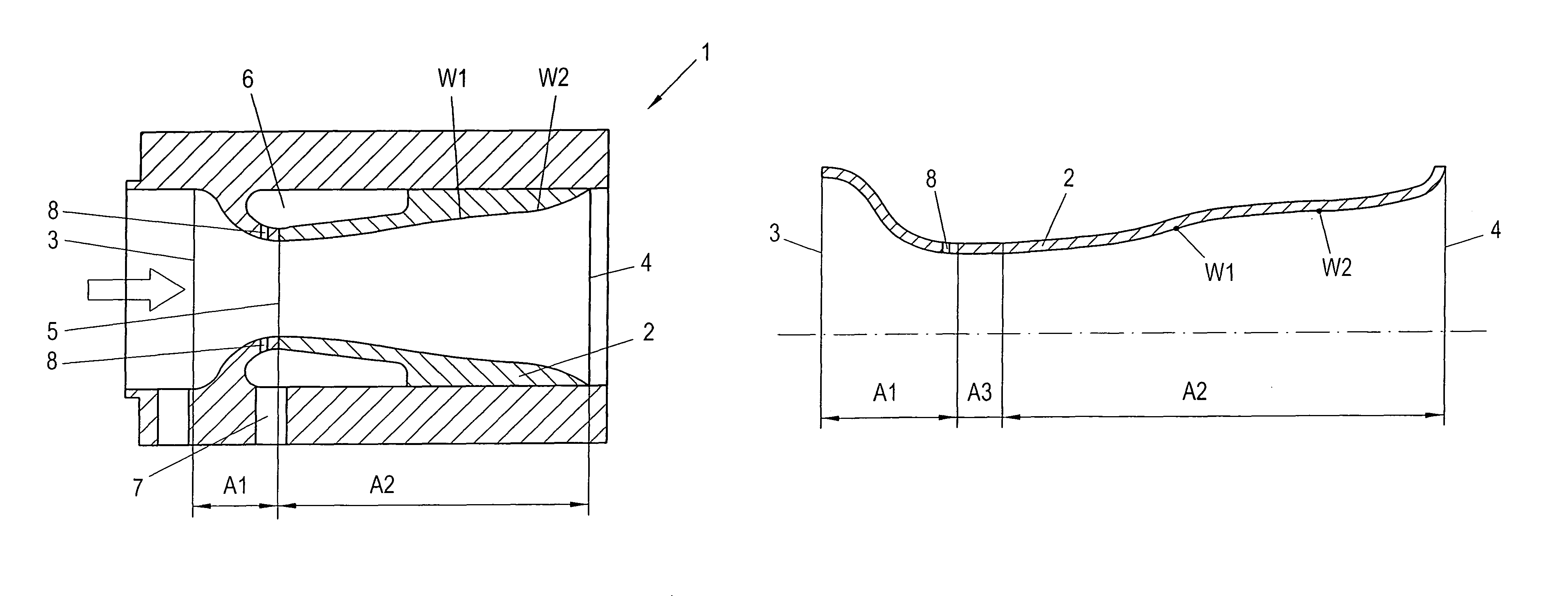
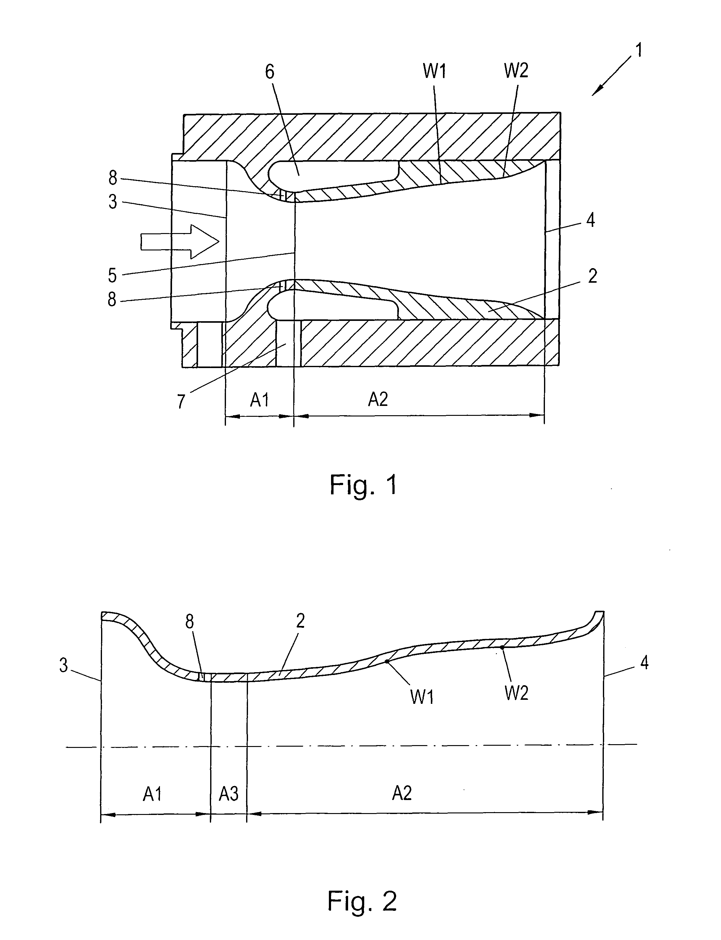
[0012]The inventive fluid mixer 1 according to FIG. 1 comprises a Venturi tube 2 which is implemented here at the same time as a housing of the fluid mixer 1. The flow direction through the fluid mixer is indicated by the arrow in FIG. 1. A first fluid, e.g. air, is fed through an inlet cross-section 3, and the fluid mixture is discharged from the fluid mixer 1 via an outlet cross-section 4.

[0013]The Venturi tube 2 comprises a convergent section A1 which extends from the inlet cross-section 3 up to the narrowest cross-section 5 of the Venturi tube 2. The narrowest cross-section 5 can also be configured as a third, cylindrical section A3, as indicated in FIG. 2. “Convergent” means here that the cross-section decreases in the flow direction, The Venturi tube 2 further comprises a second divergent section A2 which extends from the narrowest cross-section 5 of the Venturi tube 2 up to the outlet cross-section 4. “Divergent” means here that the cross-section increases in the flow directi...


PUM


Abstract

A fluid mixer in the form of a Venturi tube includes a divergent section (A2) with a steady contour curve having at least two inflection points (W1, W2) to reduce flow separations.

Description

BACKGROUND OF THE INVENTION[0001]1. Field of the Invention[0002]The present invention relates to a fluid mixer in which a first fluid flowing with subsonic speed through a Venturi tube is mixed with a second fluid fed via admixing openings, wherein in the Venturi tube, a first convergent section is provided which extends from an inlet cross-section up to the narrowest cross-section of the Venturi tube, and a second divergent section is provided which extends from the narrowest cross-section up to the outlet cross-section.[0003]2. The Prior Art[0004]Fluid mixers are used to mix two fluids, such as, e.g., air and fuel gas for a gas engine, in a desired ratio and as homogenous as possible. Such fluid mixers are usually constructed as Venturi tubes and operate in the subsonic range at substantially constant ambient pressure, Here, a first fluid, e.g., air, flows through the Venturi tube, wherein the speed of the fluid never reaches sonic speed. At the narrowest point of the Venturi tube...

Claims


Application Information

Patent Timeline
IPC IPC(8): B01F5/04
CPCB01F5/0428B01F2005/0448Y10T137/2599B01F25/312533B01F25/31242
Inventor KORNFELD, MATTHIASDOLOVAI, PETERLINDNER-SILWESTER, TINO
Owner HOERBIGER KOMPRESSORTECHNIK HLDG GMBH
Why Eureka
Try Eureka