Hand-held power tool with a dust suction module

US20050281627A1Inactive Publication Date: 2005-12-22HILTI AG

Image

  • Hand-held power tool with a dust suction module
  • Hand-held power tool with a dust suction module
  • Hand-held power tool with a dust suction module

Examples


Embodiment Construction

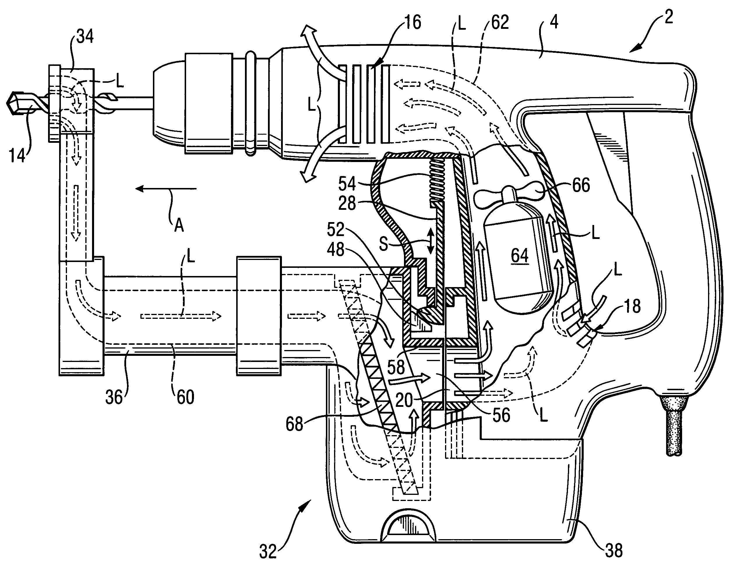
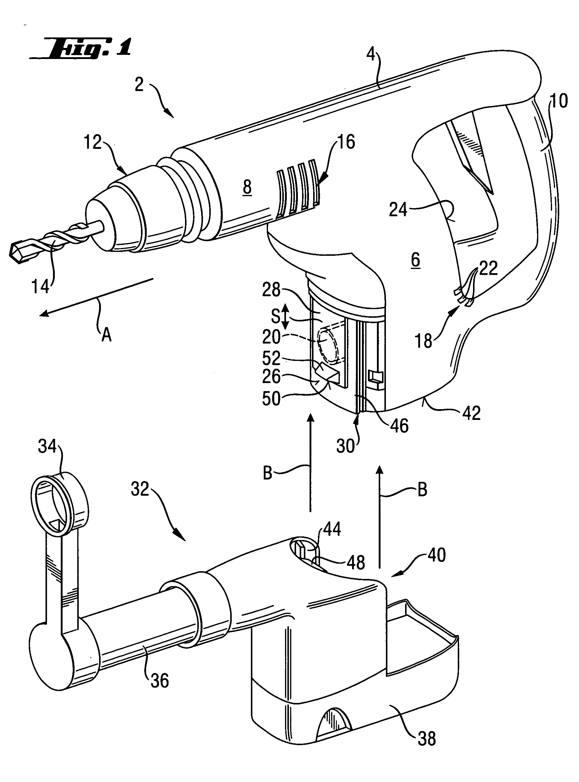
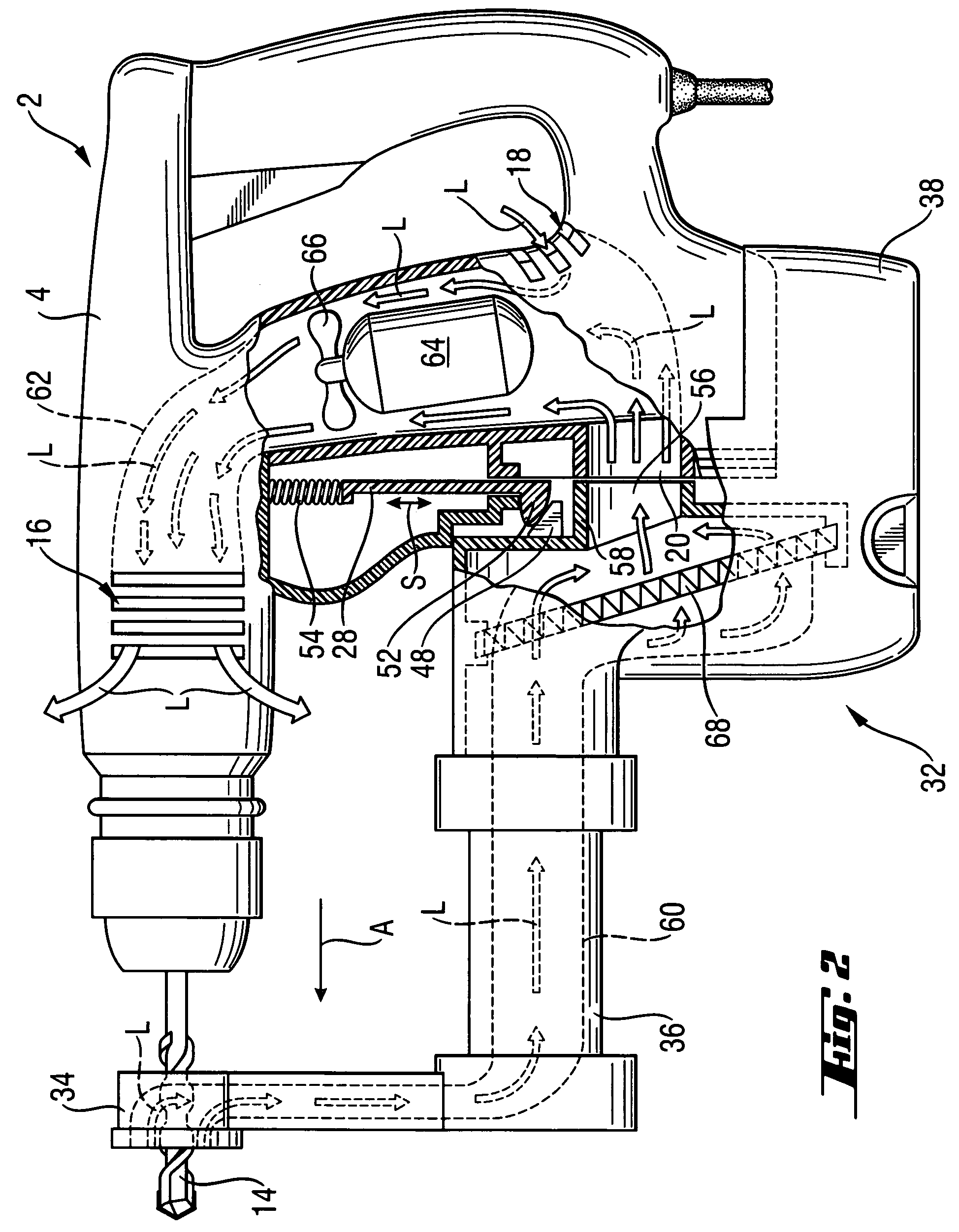
[0023] A hand-held power tool 2 according to the present invention, which is shown in FIG. 1, is formed as a drilling took, e.g., as a hammer drill and includes a housing 4 that is formed of a motor housing 6, drive gear housing 8, and a handle 10. A tool head 12, in which a working tool 14 is received, projects from the drive gear housing 8 in an operational direction A of the power tool 2.

[0024] In the drive gear housing 8, there is provided an air outlet 16 in form of a plurality of slot-shaped openings. Further, the power tool 2 has a two-part air inlet which is formed of a side opening 18 and a connection opening 20 which is shown with dash lines.

[0025] The side opening 18 is formed of a plurality of slot-shaped housing recesses 22. They are provided on a back side 24 of the motor housing 6 and face away from the working tool side end of the power tool 2 in a direction opposite the operational direction A.

[0026] The connection opening 20 is provided on a front side 26 of the...


PUM

PropertyMeasurementUnit
Displacementaaaaaaaaaa

Abstract

A hand-held power tool (2) connectable with a dust suction module (32) includes a motor (64) and an air flow generator (66) which for cooling the motor (64) is located, together with the motor (64), in air flow path (62) between an air inlet and an air outlet (16) both formed in the tool housing, (4, 6), with an air inlet having a side opening (18) and a connection opening (20) connectable with the suction path (60) of the dust suction module (32) and the dust suction module (32) having a suction conduit (58) for connecting the suction path (60) with the air flow path (62) and adjoining the connection opening (20) in a connected condition of the dust suction module (32) with the power tool, and with the power tool (2) further having a closing member provided on the connection opening (20), operable by the dust suction module (32), and having, in an attached position of the dust section module (32), an open position, and having a closed position in the detached condition of the dust suction module (32).

Description

BACKGROUND OF THE INVENTION [0001] 1. Field of the Invention [0002] The present invention relates to a hand-held power tool connectable, if necessary, with a dust suction module for aspirating the to-be-removed material produced during the operation of the power tool. [0003] 2. Description of the Prior Art [0004] The hand-held power tool, which is connectable with the dust suction module, includes a motor and an air flow generator that for cooling the motor is located, together with the motor, in a cooling flow path between an air inlet and an air outlet which are formed in the tool housing. The dust suction module is provided with a suction conduit that adjoins the inlet so that a connection between the suction path of the dust suction module and the cooling flow path can be established. [0005] Hand-held power tools of the type discussed above can be rapidly and simply equipped with a dust suction module, when needed, in order to remove material which is produced during operation o...

Claims


Application Information

Patent Timeline
22 Dec 2005
Publication
US20050281627A1
IPC
B23Q11/00; B24B23/00; B24B55/10
CPC
B23Q11/0046; Y10T408/50; B25F5/008; B24B55/10; B23Q11/127
Inventors
BRITZ, RORY