Systems and methods for exhaust catalyst temperature control

a technology of catalyst temperature control and system, applied in the direction of electrical control, machine/engine, electric control of exhaust treatment, etc., can solve the problems of reducing fuel economy, throttling losses, in-cylinder heat loss, engine knock, etc., to reduce engine knock, nox emissions, and fuel economy. improve, the effect of reducing the level of engine boos

Active Publication Date: 2016-03-29
FORD GLOBAL TECH LLC
View PDF65 Cites 19 Cited by
  • Summary
  • Abstract
  • Description
  • Claims
  • Application Information

AI Technical Summary

Benefits of technology

[0002]Engines may be configured with exhaust gas recirculation (EGR) systems to divert at least some exhaust gas from an engine exhaust manifold to an engine intake manifold. By providing a desired engine dilution, such systems reduce engine knock, throttling losses, in-cylinder heat losses, as well as NOx emissions. As a result, fuel economy is improved, especially at higher levels of engine boost. Engines have also been configured with a sole cylinder (or cylinder group) that is dedicated for providing external EGR to other engine cylinders. Therein, all of the exhaust from the dedicated cylinder group is recirculated to the intake manifold. As such, this allows a substantially fixed amount of EGR to be provided to engine cylinders at most operating conditions. By adjusting the fueling of the dedicated EGR cylinder group (e.g., to run rich), the EGR composition can be varied to include species such as Hydrogen which improve the EGR tolerance of the engine and resulting fuel economy benefits.
[0003]Engine systems with dedicated EGR cylinder groups may be configured with a diverter valve which allows all the exhaust from the dedicated EGR cylinder group to either be directed back to the intake manifold or diverted to the exhaust catalyst. An example of such a system with a diverter valve is shown by Hayman et al. in U.S. Pat. No. 8,539,768. By diverting exhaust from the dedicated EGR cylinder to the exhaust catalyst, heat flow to the catalyst can be increased, such as during engine cold-start and catalyst warm-up conditions. In addition, the EGR rate can be decreased at light loads.
[0007]In this way, a bypass valve coupled to a dedicated EGR system may be actuated to maintain an exhaust catalyst temperature. By continuously diverting at least some exhaust gas to an exhaust catalyst while recirculating a remaining portion of the exhaust gas to the engine intake, catalyst temperature control is enabled without requiring EGR to be disabled. By enriching the dedicated EGR cylinder group based on the flow through the bypass valve, catalyst heating can be expedited. By combining rich exhaust (which is hydrocarbon-enriched) from the dedicated EGR cylinder group with lean exhaust (which is oxygen-enriched) from remaining engine cylinders at the exhaust catalyst, a significant exothermic reaction can be generated to maintain the exhaust catalyst above an activation temperature. In addition, by enabling the exothermic reaction to occur directly at the exhaust catalyst, heat transfer is improved, and heat loss to other engine components (such as the cylinder head, turbine, exhaust plumbing, etc.) is reduced. By allowing catalyst temperature to be controlled without disabling EGR delivery, exhaust emissions can be improved without incurring fuel economy losses.

Problems solved by technology

However, the inventors herein have identified potential issues with such an approach.
As an example, the diverter valve may provide limited choices.
In particular, the controller may be constrained between directing all the exhaust to the intake manifold, which improves fuel economy but reduces exhaust catalyst temperature, or directing all the exhaust to the catalyst, which improves catalyst temperature but reduces fuel economy.
Thus during the redirecting of exhaust for catalyst warming, EGR is temporarily disabled, even though engine dilution may be required.
As such, this results in a drop in engine performance and fuel economy.
As such, if the exhaust catalyst temperature drops below a threshold temperature during engine operation, an emissions conversion rate is degraded, adversely affecting engine exhaust emissions.

Method used


Image

  • Systems and methods for exhaust catalyst temperature control
  • Systems and methods for exhaust catalyst temperature control
  • Systems and methods for exhaust catalyst temperature control

Examples


Embodiment Construction

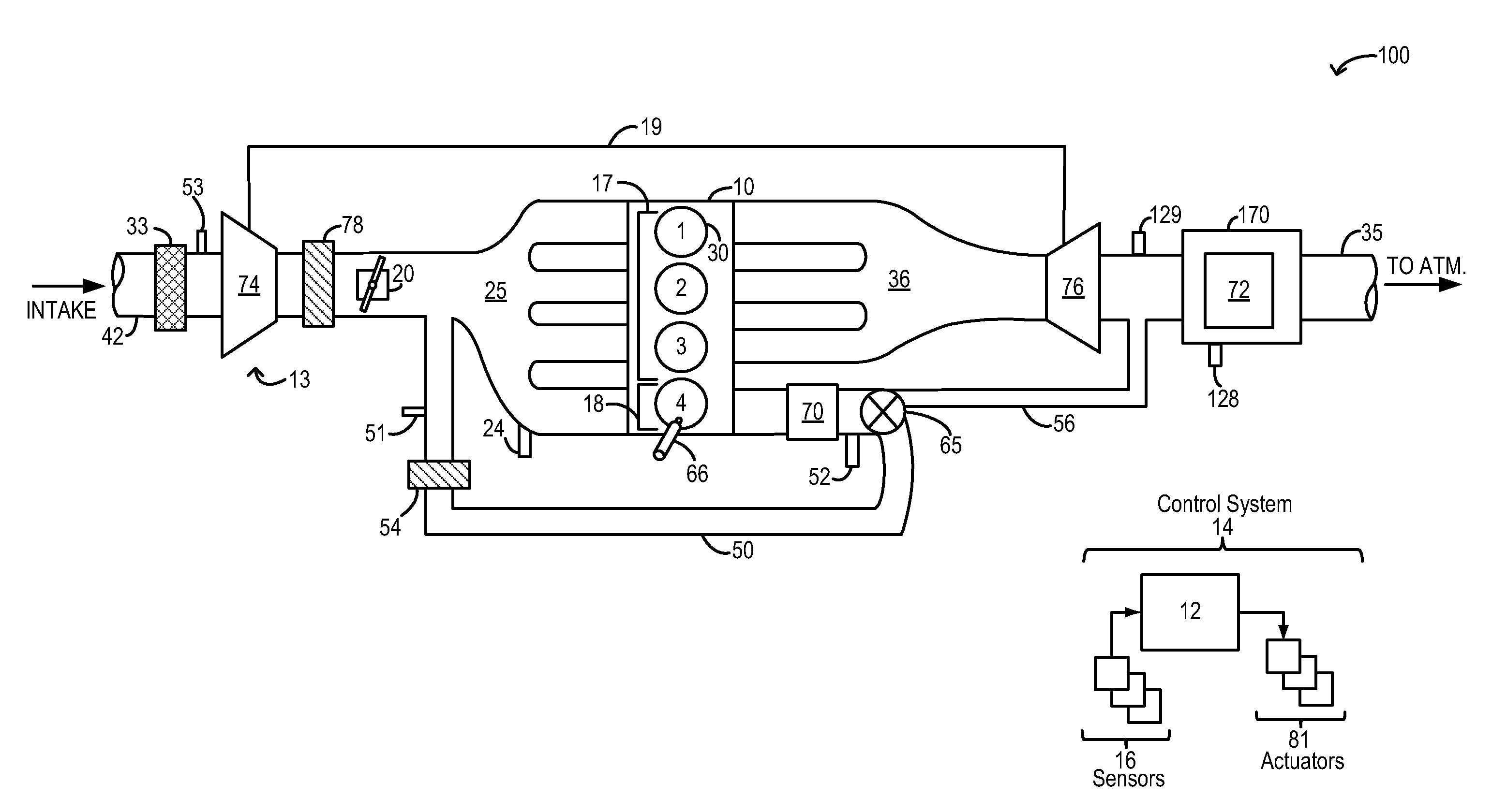
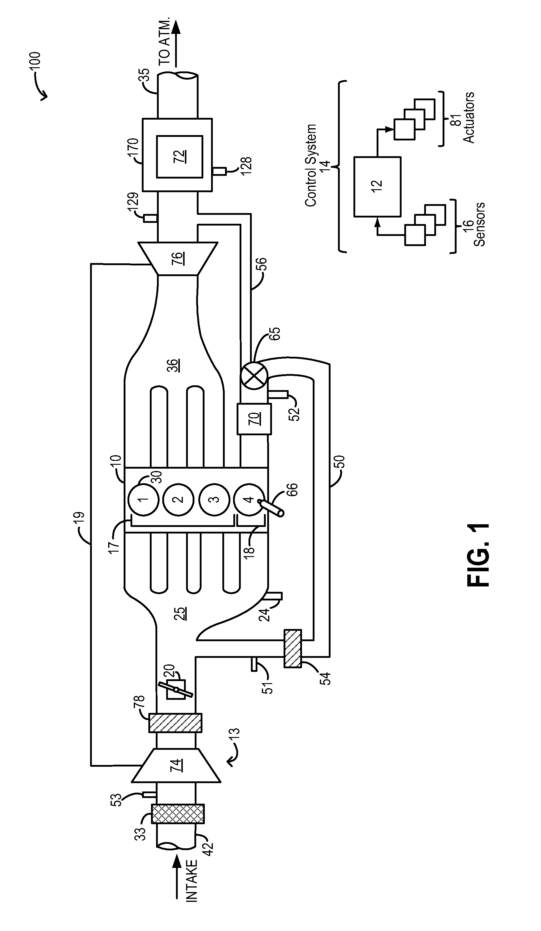
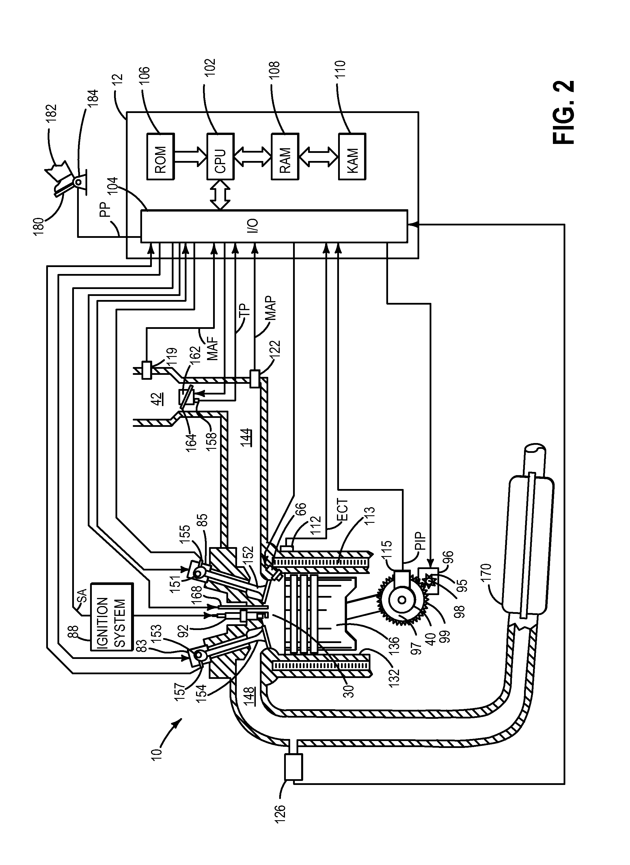
[0013]The present description is related to exhaust catalyst temperature control on an engine operating with highly diluted cylinder mixtures, such as the engine systems of FIGS. 1-2, wherein exhaust from a dedicated cylinder group is used to provide external EGR to the engine. A controller may be configured to perform a control routine, such as the routine of FIG. 3 to continually vary a proportion of exhaust diverted from the dedicated cylinder group to an exhaust catalyst, while bypassing remaining engine cylinders, relative to exhaust recirculated to the engine intake, based on catalyst temperature. In doing so, the exhaust catalyst can be maintained above an operational temperature while EGR is delivered. An example adjustment for exhaust catalyst temperature control during engine operation, including during and after an engine cold-start, is shown with reference to FIG. 4.

[0014]FIG. 1 schematically shows aspects an example engine system 100 including an engine 10 with four cyl...


PUM


Abstract

Methods and systems are provided for exhaust catalyst temperature control by metering exhaust bypass flow from a dedicated EGR cylinder. A continuously variable bypass valve may be adjusted to vary an amount of exhaust directed to an exhaust catalyst from a dedicated EGR cylinder via a bypass passage relative to exhaust recirculated to the engine intake via an EGR passage. At lower catalyst temperatures, more exhaust is metered via the bypass passage to enable catalyst temperature to be maintained above an activation level.

Description

FIELD[0001]The present description relates to systems and methods for improving exhaust catalyst temperature control in engine systems configured with a sole cylinder for providing external EGR to other engine cylinders.BACKGROUND AND SUMMARY[0002]Engines may be configured with exhaust gas recirculation (EGR) systems to divert at least some exhaust gas from an engine exhaust manifold to an engine intake manifold. By providing a desired engine dilution, such systems reduce engine knock, throttling losses, in-cylinder heat losses, as well as NOx emissions. As a result, fuel economy is improved, especially at higher levels of engine boost. Engines have also been configured with a sole cylinder (or cylinder group) that is dedicated for providing external EGR to other engine cylinders. Therein, all of the exhaust from the dedicated cylinder group is recirculated to the intake manifold. As such, this allows a substantially fixed amount of EGR to be provided to engine cylinders at most ope...

Claims


Application Information

Patent Timeline
Patent Type & Authority Patents(United States)
IPC IPC(8): F01N3/00F02D41/00F01N9/00
CPCF02D41/0052F01N9/00F02M26/14F02M26/43F01N2900/1602F02D41/008F02D41/024F02D41/0255F02D41/0055F02M26/16F02M26/46F02M26/05F02M26/15Y02T10/12Y02T10/40F02M26/02F02D41/00F02D43/00
Inventor HILDITCH, JAMES, ALFREDSHELBY, MICHAEL, HOWARDSTYLES, DANIEL, JOSEPHGLUGLA, CHRIS, PAULCZEKALA, MICHAEL, DAMIAN
Owner FORD GLOBAL TECH LLC
Why Eureka
Try Eureka