Systems and methods for transient control

a transient control and system technology, applied in the direction of electric control, machines/engines, output power, etc., can solve the problems of reducing the peak torque capability of the engine, reducing the efficiency of the catalyst, and the use of the diverter valve may be cost prohibitive, so as to reduce the knock of the engine, reduce the loss of throttling, and reduce the nox emissions of the in-cylinder heat loss, the effect of fuel economy improvemen

Active Publication Date: 2016-04-14
FORD GLOBAL TECH LLC
View PDF6 Cites 29 Cited by
  • Summary
  • Abstract
  • Description
  • Claims
  • Application Information

AI Technical Summary

Benefits of technology

[0002]Engines may be configured with exhaust gas recirculation (EGR) systems to divert at least some exhaust gas from an engine exhaust manifold to an engine intake manifold. By providing a desired engine dilution, such systems reduce engine knock, throttling losses, in-cylinder heat losses, as well as NOx emissions. As a result, fuel economy is improved, especially at higher levels of engine boost. Engines have also been configured with a sole cylinder (or cylinder group) that is dedicated for providing external EGR. Therein, all of the exhaust from the dedicated cylinder group is recirculated to the intake manifold. As such, this allows a substantially fixed amount of EGR to be provided to engine cylinders at most operating conditions. By adjusting the fueling of the dedicated EGR cylinder group (e.g., to run rich), the EGR composition can be varied to include species such as hydrogen which improve the EGR tolerance of the engine and result in fuel economy benefits.
[0003]While the availability of EGR over a larger operating range provides fuel economy benefits, the fixed EGR rate also reduces the peak torque capability of the engine. In addition, catalyst warm-up may be degraded, particularly after an engine cold-start.
[0006]In one example, the above issues may be at least partly addressed by a method for an engine comprising: transitioning into and out of dedicated EGR cylinder operation while adjusting each of an intake throttle and an exhaust wastegate in opposing directions. In this way, torque transients incurred while EGR from a dedicated EGR cylinder is ramped-up or down, and while a dedicated EGR cylinder is activated and deactivated, can be decreased.
[0007]As an example, an engine system may be configured with a single dedicated EGR cylinder for providing external EGR to all engine cylinders. During conditions where EGR demand is low, such as when transitioning from a lower engine load to a higher engine load, the engine may be transitioned out of dedicated EGR cylinder operation by diverting exhaust from the dedicated EGR cylinder away from the EGR passage and engine intake, and towards the exhaust passage, upstream of an exhaust turbine. By redirecting exhaust away from the EGR passage, engine dilution provided by the dedicated EGR cylinder is reduced. Deactivating the EGR cylinder also results in engine output torque initially decreasing. Then, as the EGR in the intake manifold is used up and replaced with fresh air, the engine output torque increases. To reduce the torque unevenness involved with the transition out of dedicated EGR cylinder operation, during the transition from the lower engine load to the higher engine load, after switching exhaust from the dedicated EGR cylinder towards the exhaust turbine, each of an intake throttle and an exhaust wastegate are modulated to expedite purging of residuals from the intake manifold and refilling of the intake manifold with fresh air. The throttle and wastegate adjustment may be performed when the dedicated EGR cylinder is reactivated during an engine start only after an emission control device reaches a threshold temperature, such as a light-off temperature.
[0009]In this way, external EGR can be varied by diverting exhaust from the dedicated EGR cylinder away from the intake, while reducing torque unevenness during the activating or deactivating using engine actuator adjustments. By subsequently adjusting the intake throttle position, the wastegate position, the spark timing, and the cam timing to “base” positions before the transition is completed, a torque surge anticipated when the EGR is replaced with fresh air can be averted. By reducing torque unevenness during conditions when EGR is ramped in or ramped out from a dedicated EGR cylinder, a smoother transition is enabled and engine performance is improved.

Problems solved by technology

While the availability of EGR over a larger operating range provides fuel economy benefits, the fixed EGR rate also reduces the peak torque capability of the engine.
In addition, catalyst warm-up may be degraded, particularly after an engine cold-start.
However, the use of diverter valves may be cost prohibitive.
In addition, they may have durability issues.
However, the inventors herein have recognized potential issues with the above approaches.
As an example, during transitions when exhaust flow from the dedicated EGR cylinder is being directed to the intake or redirected to the exhaust, such as when the dedicated EGR cylinder is being reactivated or deactivated, torque disturbances may be experienced.
As such, it may be difficult to reduce the torque disturbances while concurrently maintaining accurate control of other engine operating parameters, such as air-fuel ratio, spark timing, and cam timing.
This results in conflicting torque changes as the exhaust being redirected to the pre-turbine location may increase peak torque while a delay in purging of EGR from the intake manifold results in torque loss from the dedicated EGR cylinder.
As an example, even after exhaust from the dedicated EGR cylinder has been redirected away from the intake manifold, and intake airflow has been increased, due to delays in manifold filling, there may be a corresponding delay in purging EGR from the engine intake.
As another example, when EGR is desired and dedicated EGR operation is re-activated, the same delay in manifold filling may result in lower engine dilution than desired, and a resulting torque excursion.
As such, until the EGR has been ramped up to the desired rate, there may be torque unevenness.
Deactivating the EGR cylinder also results in engine output torque initially decreasing.

Method used


Image

  • Systems and methods for transient control
  • Systems and methods for transient control
  • Systems and methods for transient control

Examples


Embodiment Construction

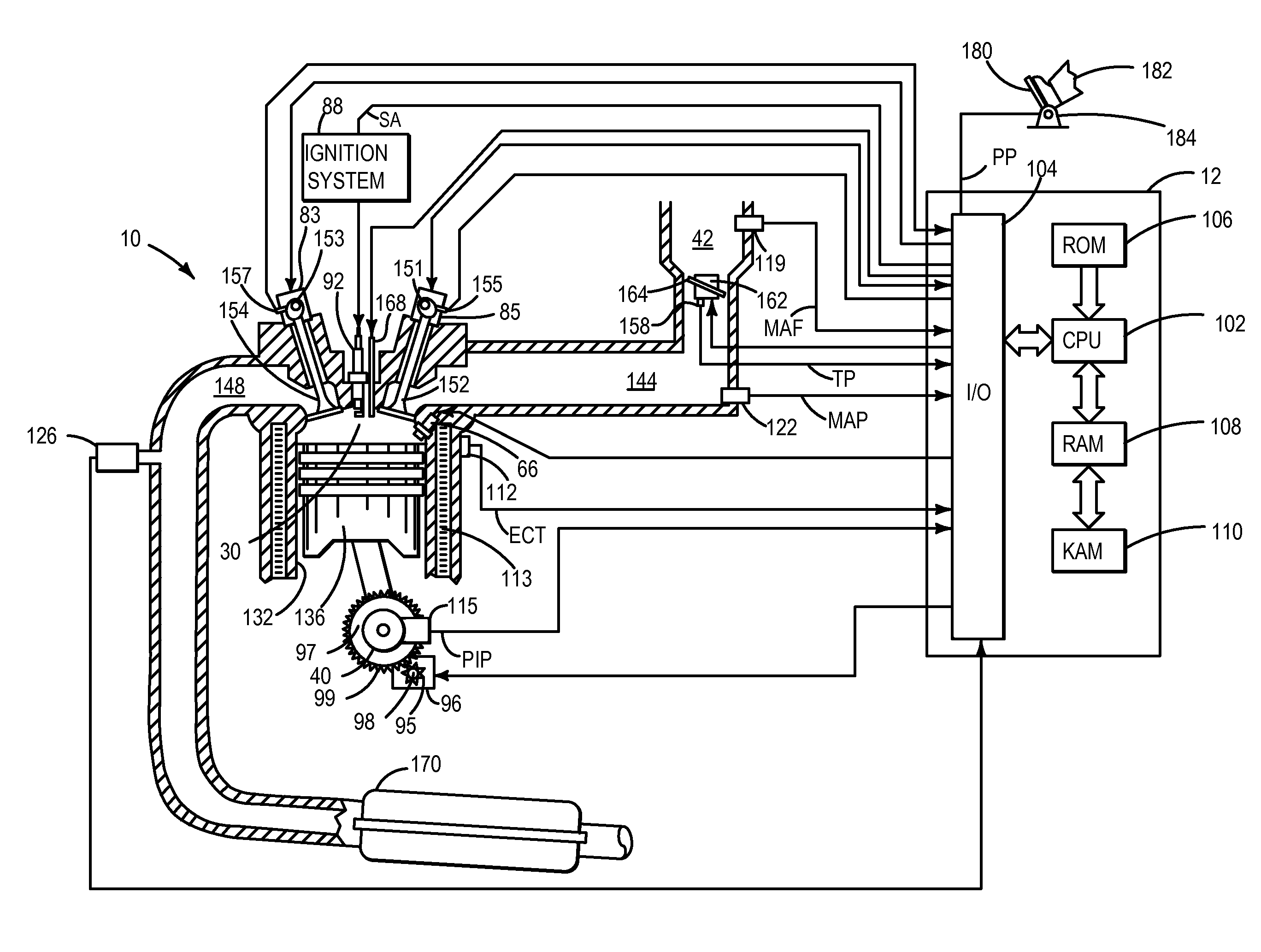
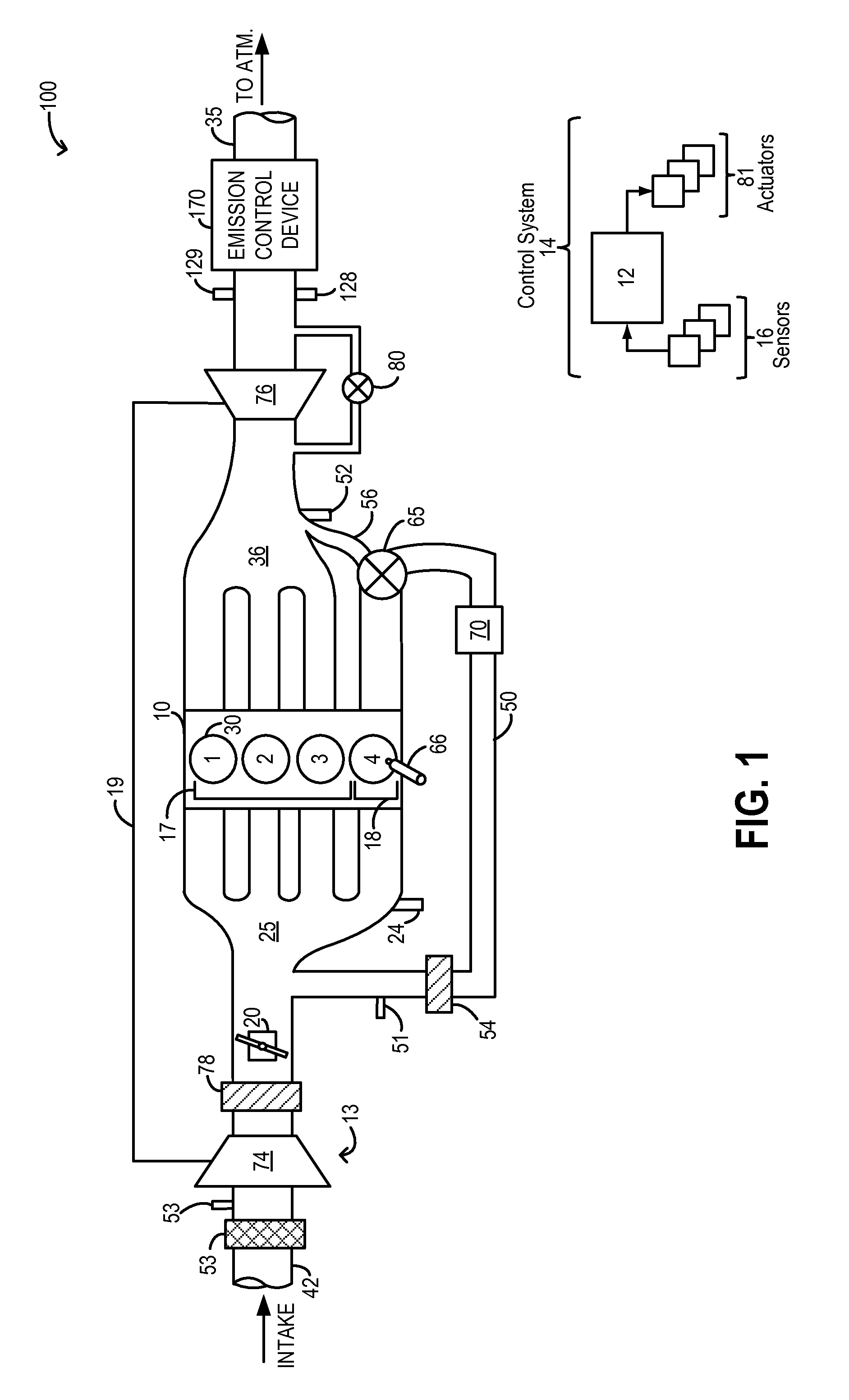
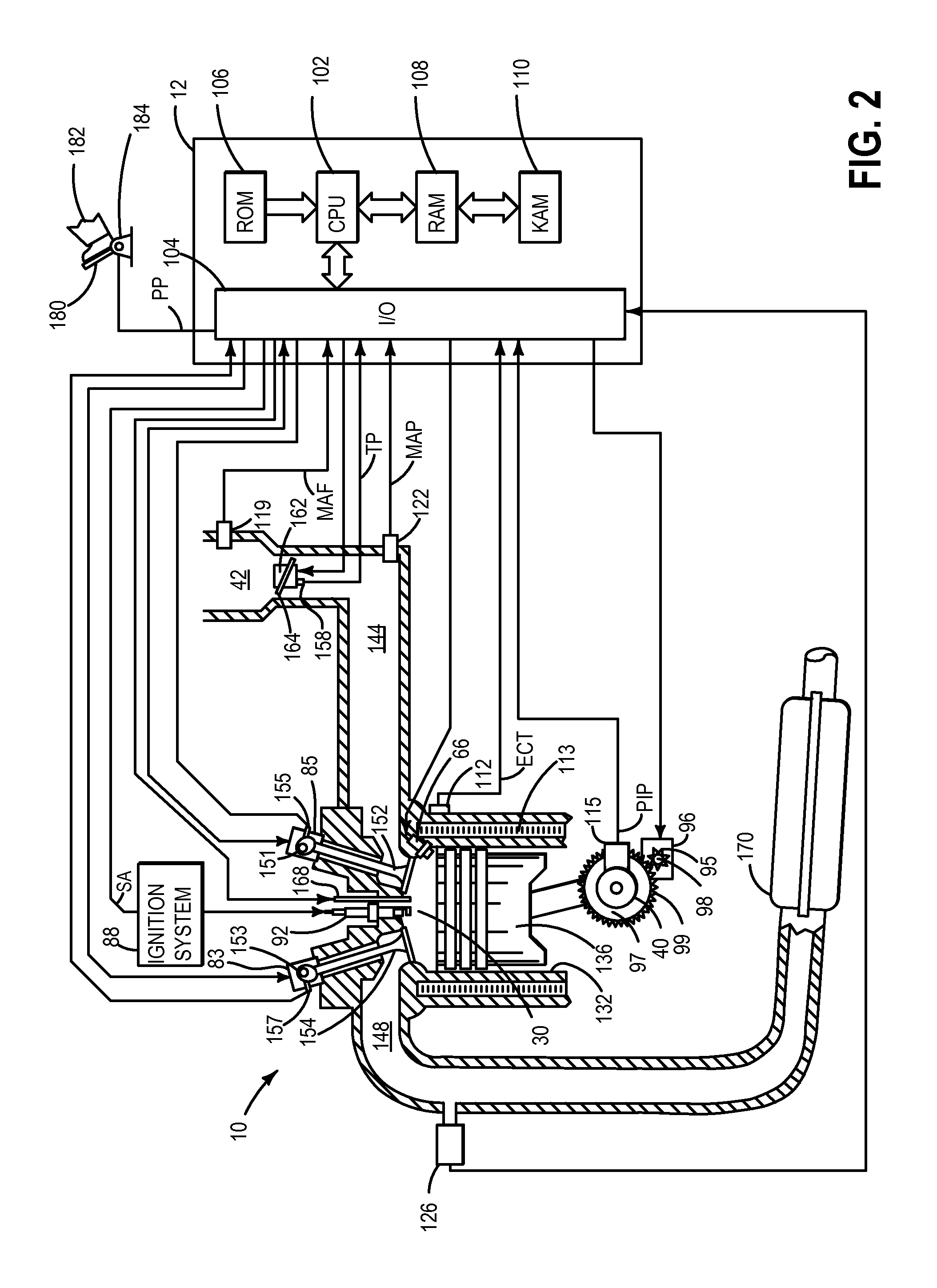
[0016]The present description is related to EGR flow control on an engine operating with highly diluted cylinder mixtures, such as the engine systems of FIGS. 1-2. The engine cylinder mixtures may be diluted using recirculated exhaust gases (EGR) that are byproducts of combusting air-fuel mixtures. In response to an increase or decrease in EGR demand, such as responsive to a change in engine load, exhaust from the dedicated EGR cylinder group may be diverted to or away from the engine intake. A controller may be configured to perform a control routine, such as the routine of FIGS. 3-4, during a transition between dedicated EGR cylinder operating modes, to reduce torque transients and enable a smooth transition. Therein, the controller may coordinate the adjustment of multiple engine actuators, such as an intake throttle, an exhaust wastegate, spark timing, cam timing and valve timing, during the transition as EGR flow from the dedicated EGR cylinder group varies, to reduce torque tr...


PUM


Abstract

Methods and systems are provided for reducing torque transients experienced when a dedicated EGR cylinder is transitioned in to or out of dedicated EGR mode. During a transition, each of an intake throttle and a wastegate is adjusted in opposing directions. Throttle and wastegate adjustments are coordinated with adjustments to spark timing and intake cam timing to provide sufficient torque reserve for the transition.

Description

FIELD[0001]The present description relates to systems and methods for improving torque transients in engine systems configured with a dedicated cylinder group for providing external EGR to other engine cylinders.BACKGROUND AND SUMMARY[0002]Engines may be configured with exhaust gas recirculation (EGR) systems to divert at least some exhaust gas from an engine exhaust manifold to an engine intake manifold. By providing a desired engine dilution, such systems reduce engine knock, throttling losses, in-cylinder heat losses, as well as NOx emissions. As a result, fuel economy is improved, especially at higher levels of engine boost. Engines have also been configured with a sole cylinder (or cylinder group) that is dedicated for providing external EGR. Therein, all of the exhaust from the dedicated cylinder group is recirculated to the intake manifold. As such, this allows a substantially fixed amount of EGR to be provided to engine cylinders at most operating conditions. By adjusting th...

Claims


Application Information

Patent Timeline
Patent Type & Authority Applications(United States)
IPC IPC(8): F02M25/07
CPCF02M25/0704F02B37/18F02D13/0219F02D37/02F02D41/0007F02D41/005F02D41/006F02D41/008F02D41/307F02D2041/001F02D2041/0017F02M26/02F02M26/43Y02T10/12Y02T10/40
Inventor STYLES, DANIEL JOSEPHGLUGLA, CHRIS PAULLEONE, THOMAS G.MCCONVILLE, GREGORY PATRICKHILDITCH, JAMES ALFRED
Owner FORD GLOBAL TECH LLC
Why Eureka
Try Eureka