Illumination device and projector

a technology of projection device and projector, which is applied in the direction of picture reproducers using projection devices, lighting and heating apparatus, instruments, etc., can solve the problems of difficult degradation of wavelength conversion efficiency of fluorescent layer, difficult to suppress rise in temperature of fluorescent layer, and difficult to reduce the intensity of light variation, so as to achieve high-quality fluorescence. , the effect of reducing the variation of light intensity

Active Publication Date: 2016-03-29
SEIKO EPSON CORP
View PDF11 Cites 16 Cited by
  • Summary
  • Abstract
  • Description
  • Claims
  • Application Information

AI Technical Summary

Benefits of technology

[0008]An advantage of some aspects of the invention is to provide an illumination device and a projector, each of which emit high-quality fluorescence. In the illumination device and in the projector, it is hard to cause the deterioration of the fluorescent layer and the degradation of the wavelength conversion efficiency of the fluorescent layer, because the rise in temperature of the fluorescent layer is suppressed with a simple structure suitable for downsizing.

Problems solved by technology

Therefore, rise in temperature of the fluorescent layer is suppressed, and deterioration in the fluorescent layer and degradation of wavelength conversion efficiency of the fluorescent layer are hard to occur compared to the case in which a certain part is continuously irradiated with the excitation light.
In other words, since a certain part of the fluorescent layer is repeatedly irradiated with the excitation light in every round at short time intervals, the part is not sufficiently cooled, and it becomes unachievable to sufficiently suppress the rise in temperature of the fluorescent layer.
As a result, there arise the deterioration of the fluorescent layer and the degradation of the wavelength conversion efficiency of the fluorescent layer.
Therefore, the structure thereof is complicated, which poses a problem for downsizing of the projector.
Therefore, the illumination device having the fluorescent layer difficult to be deteriorated and to be degraded in the wavelength conversion efficiency can be provided.
Therefore, the illumination device which has longer operating life and is difficult to cause the variation in luminance during the lighting period can be provided.
Therefore, the illumination device having the fluorescent layer difficult to be deteriorated and to be degraded in the wavelength conversion efficiency can be provided.
According to this configuration, the projector provided with the illumination device which has longer operating life and is difficult to cause the variation in luminance during the lighting period can be provided.

Method used


Image

  • Illumination device and projector
  • Illumination device and projector
  • Illumination device and projector

Examples


first embodiment

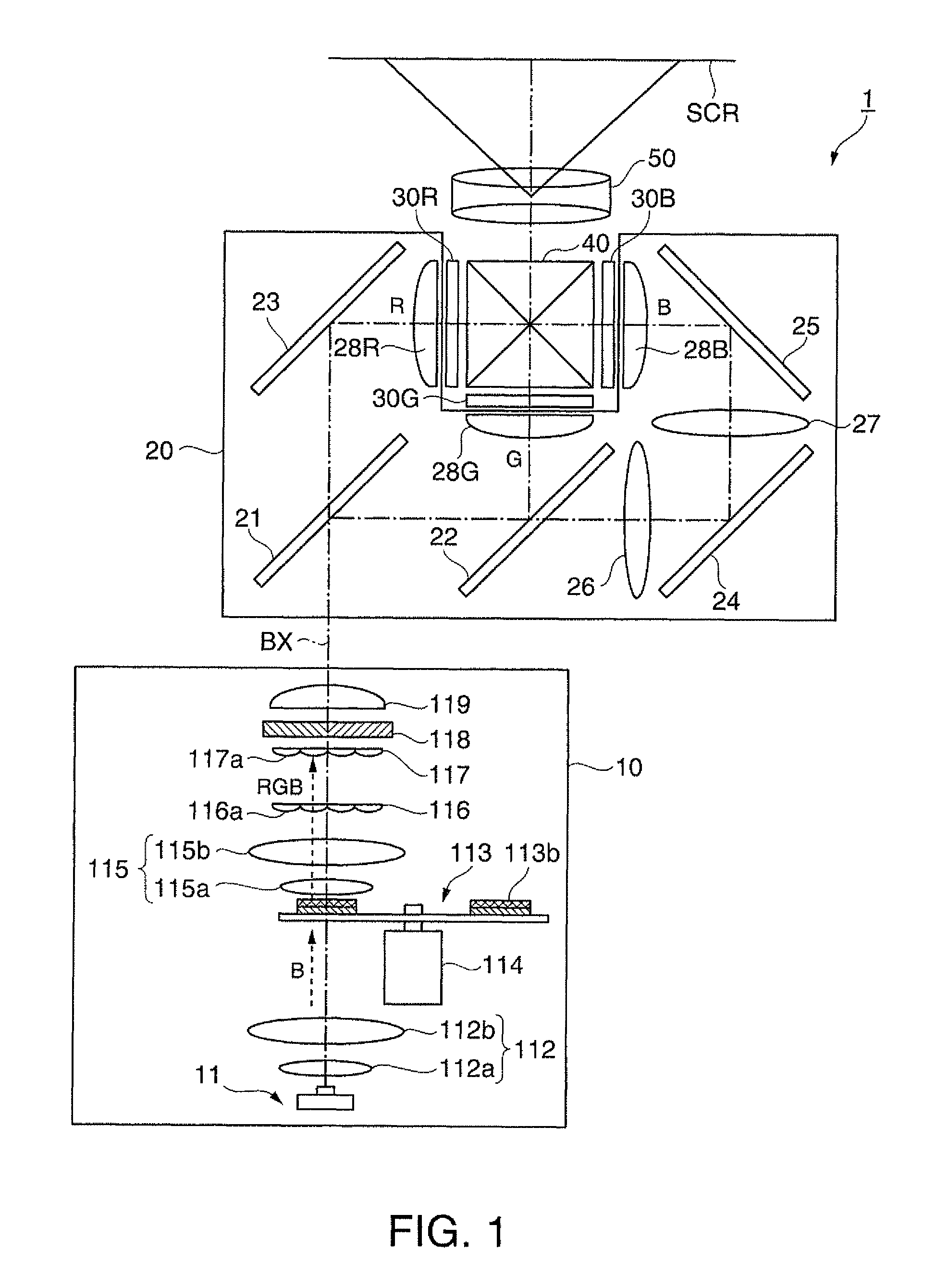
[0065]FIG. 1 is a schematic diagram schematically showing an overall configuration of a projector according to a first embodiment of the invention.

[0066]As shown in the drawing, the projector 1 is provided with an illumination device 10, a color separation light guide optical system 20, a red liquid crystal display element 30R, a green liquid crystal display element 30G, a blue liquid crystal display element 30B, a cross dichroic prism 40, and a projection optical system 50. It should be noted that hereinafter the red liquid crystal display element 30R, the green liquid crystal display element 30G, and the blue liquid crystal display element 30B might collectively be described as a liquid crystal display element 30. The liquid crystal display element 30 is a light modulation element.

[0067]The projector 1 projects image light based on an image signal externally supplied toward a screen SCR to thereby display the image on the screen SCR.

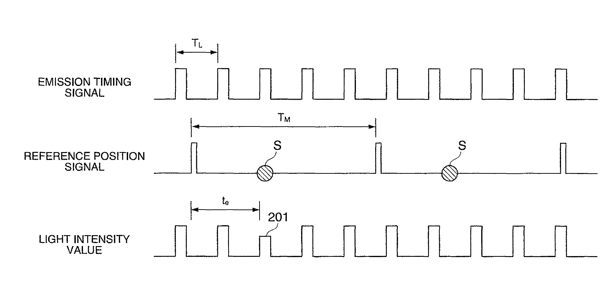
[0068]The illumination device 10 emits a white l...

second embodiment

[0125]Then, a projector according to a second embodiment of the invention will be explained. The overall configuration of the projector according to the present embodiment is substantially the same as that of the projector 1 according to the first embodiment shown in FIG. 1. It should be noted that the projector according to the present embodiment is different from the projector 1 according to the first embodiment in the control system. Hereinafter, in the explanation of the configuration, the constituents the same as those in the first embodiment will be denoted by the same reference symbols, and the explanation therefor will be omitted.

[0126]FIG. 6 is a block diagram showing a functional configuration of the control system for controlling an operation of the projector according to the present embodiment. It should be noted that in the drawing, only the constituents necessary for the explanation are extracted from the constituents shown in FIG. 1, and are illustrated in a simplifie...

third embodiment

[0158]FIG. 10 is a schematic diagram of a projector 1b according to a third embodiment.

[0159]The projector 1b is provided with a red light source device 10R, a green light source device 10G, a blue light source device 10B, the red liquid crystal display element 30R, the green liquid crystal display element 30G, and the blue liquid crystal display element 30B, a color combining optical system 40, and the projection optical system 50.

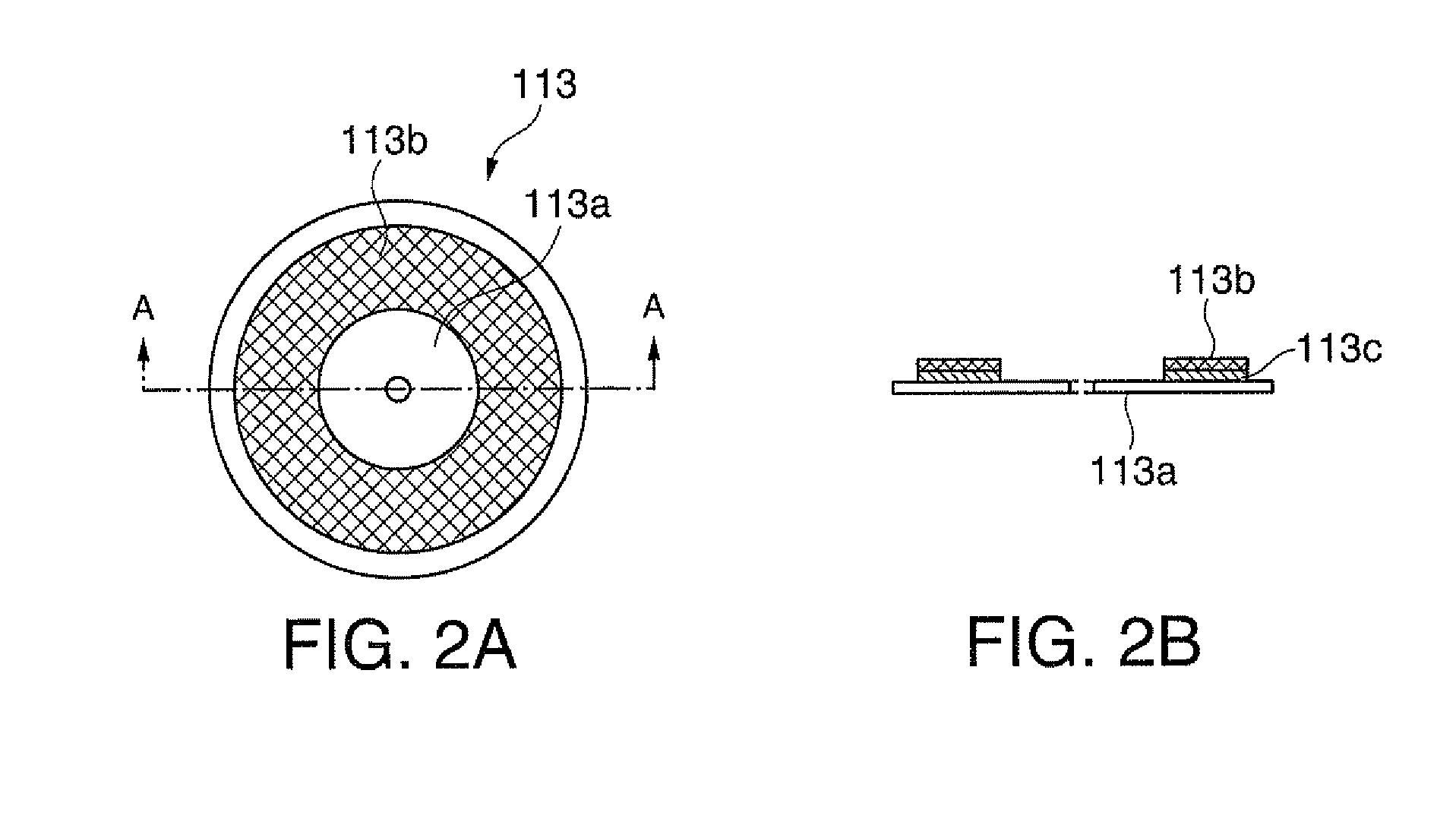
[0160]The green light source device 10G is provided with a light source 11a, a collecting lens 12a, a collimating lens 12b, a rotating fluorescent plate 13, an electric motor 14, a pickup optical system 15, a dichroic mirror 16, a collecting lens 17, a rod integrator 18, and a collimating lens 19.

[0161]The light source 11a is a solid-state light source array having optical elements, each composed of a solid-state light source 35 and a collimating lens 36 for collimating the light emitted from the solid-state light source 35, arranged in a 5×5 two-dimensio...


PUM


Abstract

An illumination device includes a substrate including a fluorescent layer, and capable of rotating around a predetermined rotary shaft, a light source adapted to emit an excitation light adapted to excite the fluorescent layer, and a control device adapted to control emission of the light source so that, when the substrate is rotating, a first area of the fluorescent layer is irradiated with the excitation light in one round, and at least a part of the first area is not irradiated with the excitation light in another round.

Description

BACKGROUND[0001]1. Technical Field[0002]The present invention relates to an illumination device and a projector.[0003]2. Related Art[0004]As an illumination device for a projector, there have been known an illumination device described in JP-A-2009-277516 (Document 1) and an illumination device described in JP-A-2010-164846 (Document 2). In either of the illumination devices, the fluorescent body is excited by excitation light emitted from the light source to thereby emit fluorescence from the fluorescent body. In the illumination device of Document 1, a fluorescent layer is provided on a rotatable substrate (a fluorescent wheel). In the illumination device of Document 2, a fan-shaped fluorescent body for emitting red fluorescence, a fan-shaped fluorescent body for emitting blue fluorescence, and a fan-shaped fluorescent body for emitting green fluorescence are disposed on a rotatable fluorescent wheel so as to form a circle. In either of the illumination devices, the lights used as...

Claims


Application Information

Patent Timeline
Patent Type & Authority Patents(United States)
IPC IPC(8): G03B21/14H04N9/31G03B33/08G03B21/20G02B26/00G02B7/00G02B27/14
CPCH04N9/3155G02B7/006G02B26/008G03B21/204G03B33/08G02B27/149
Inventor KASHIWAGI, AKIHIROMIYAMAE, AKIRA
Owner SEIKO EPSON CORP
Why Eureka
Try Eureka