

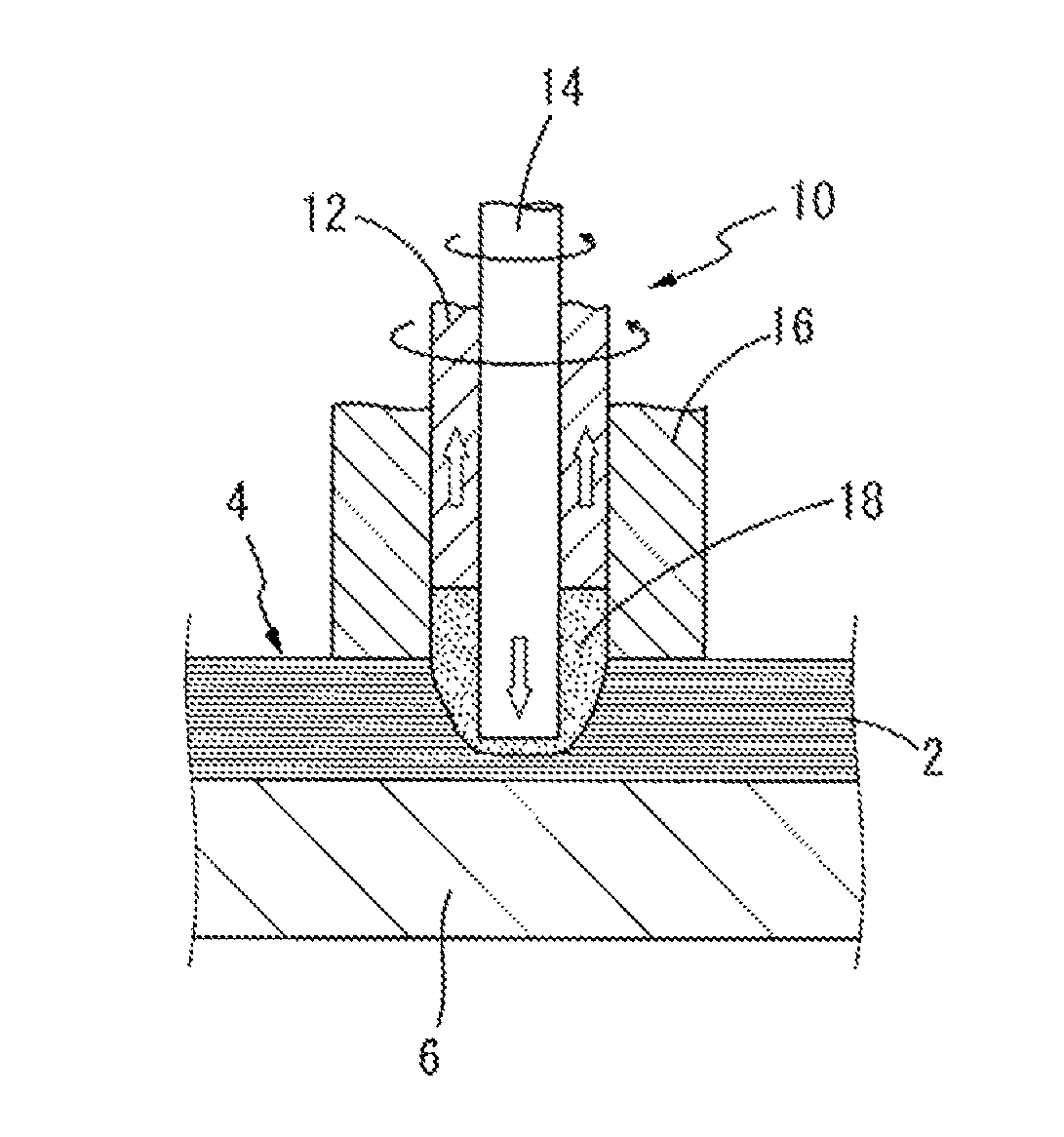
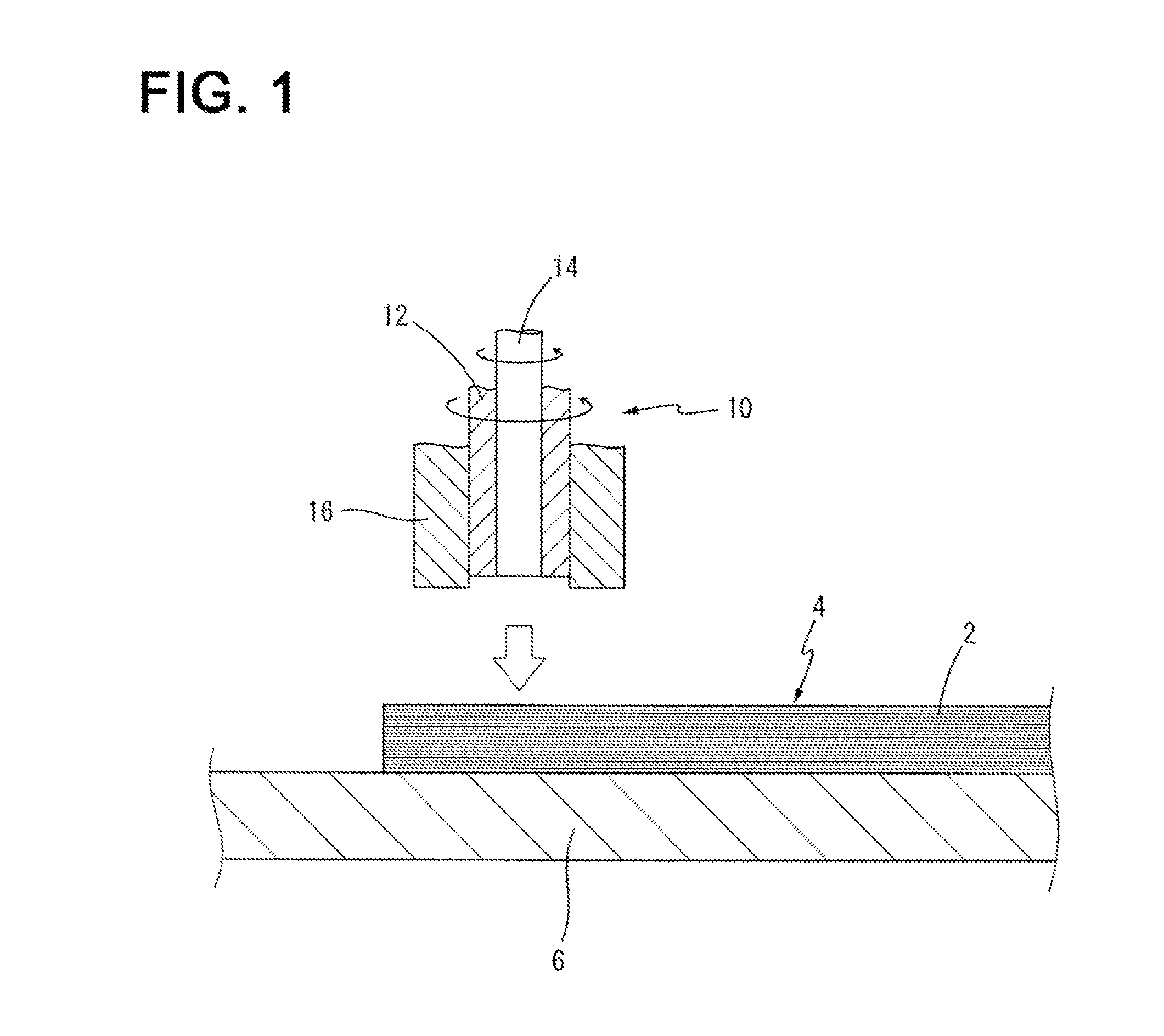
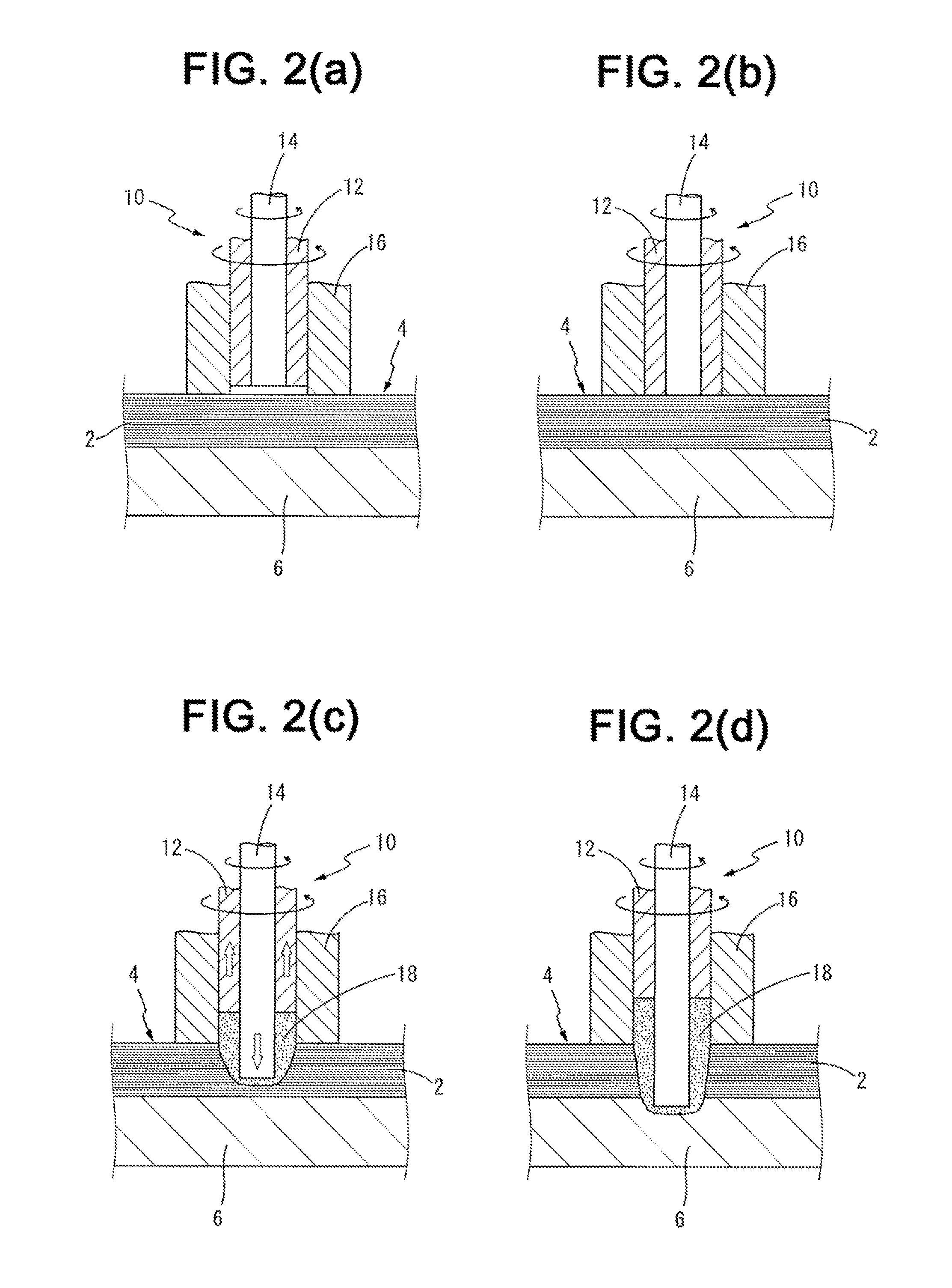
Process for spot-joining stacked metal foils
a metal foil and stacked technology, applied in metal-working equipment, welding equipment, manufacturing tools, etc., can solve the problems of undetectable low strength, risk of delamination of the stack of metal foils, and achieve the effect of advantageously improving the soundness of the obtained weld and effectively restricting or preventing problems
- Summary
- Abstract
- Description
- Claims
- Application Information
AI Technical Summary
Benefits of technology
Problems solved by technology
Method used
Image

Examples
examples
[0050]To clarify the invention more specifically, typical examples of the invention will be described. It is to be understood that the invention is not limited to the details of the illustrated examples.
[0051]Initially, various kinds of metal foil (2), upper metal sheet (8) and lower metal sheet (6) were provided and combined as Examples 1 to 6 as shown in Table 1 given below. Each of the metal foil (2), upper metal sheet (8) and lower metal sheet (6) has a dimension of 80 mm×80 mm, and a stack (4) is constituted by 40 metal foils (2) superposed on each other.
[0052]
TABLE 1UpperMetal Foil (2)Metal Sheet (8)Lower Metal Sheet (6)ThicknessNumberThicknessThickness:Material(μm)(sheets)Material(mm)Materialb (mm)Example 1JIS5040JIS0.3JIS2A3003A3003A3003Al AlloyAl AlloyAl AlloyExample 2JIS4040——JIS1A1200A3003AluminumAl AlloyExample 3JIS3040——JIS0.5A8079A3003Al AlloyAl AlloyExample 4Tough1540Tough0.5Tough2PitchPitchPitchCopperCopperCopperExample 5JIS5040JIS0.3JIS2A3003A3003A3003Al AlloyAl All...
PUM
| Property | Measurement | Unit |
|---|---|---|
| thickness | aaaaa | aaaaa |
| thickness | aaaaa | aaaaa |
| thickness | aaaaa | aaaaa |
Abstract
Description
Claims
Application Information