Steam turbine plant, combined cycle plant provided with same, and method of operating steam turbine plant

a technology of combined cycle and steam turbine, which is applied in the direction of steam engine plants, machines/engines, mechanical equipment, etc., can solve the problems of large amount of heat required to raise the temperature, and achieve the effect of increasing the efficiency of steam turbine plants and increasing the output obtained from the entire steam turbine group

Active Publication Date: 2018-01-04
MITSUBISHI HEAVY IND LTD
View PDF0 Cites 9 Cited by
  • Summary
  • Abstract
  • Description
  • Claims
  • Application Information

AI Technical Summary

Benefits of technology

[0026]In an aspect of the present invention, much high temperature steam can be supplied to the first steam turbine even when the steam which has been heated by the reheaters is being supplied to the second steam turbine. Thus, according to an aspect of the present invention, an output obtained from the entire steam turbine group can be increased and thus efficiency of a steam turbine plant can be increased.

Problems solved by technology

On the other hand, in the high-pressure evaporator, the specific heat of a fluid at a temperature near a high-pressure maximum temperature is large, and a large amount of heat is required to raise the temperature.

Method used


Image

  • Steam turbine plant, combined cycle plant provided with same, and method of operating steam turbine plant
  • Steam turbine plant, combined cycle plant provided with same, and method of operating steam turbine plant
  • Steam turbine plant, combined cycle plant provided with same, and method of operating steam turbine plant

Examples


first embodiment

[0037]“First Embodiment of Steam Turbine Plant”

[0038]First, a first embodiment of a steam turbine plant according to the present invention will be described with reference to FIGS. 1 to 3.

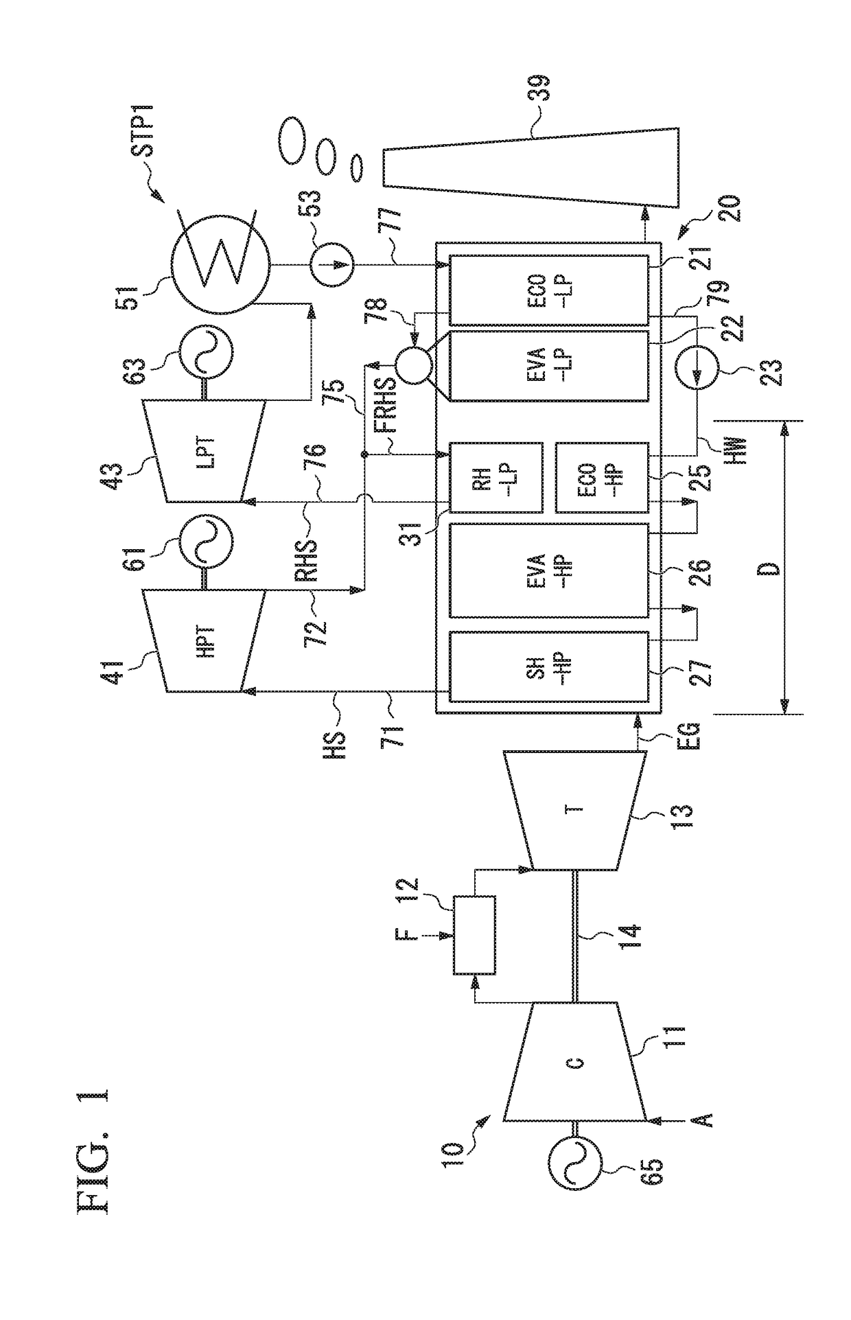
[0039]As shown in FIG. 1, a steam turbine plant STP1 in this embodiment includes a waste heat recovery boiler 20 configured to generate steam using heat of an exhaust gas EG (a heated fluid) from a gas turbine 10, steam turbines 41 and 43 driven using the steam which has been generated by a waste heat recovery boiler 20, generators 61 and 63 configured to generate electricity using driving of the steam turbines 41 and 43, a steam condenser 51 configured to convert steam used to drive the steam turbines 41 and 43 into water, a water supply pump 53 configured to return water in the steam condenser 51 to a waste heat recovery boiler 20, and a chimney 39 configured to discharge the exhaust gas EG which has passed through the waste heat recovery boiler 20 to the atmosphere. Note that, here, a combined c...

second embodiment

[0067]“Second Embodiment of Steam Turbine Plant”

[0068]Next, a second embodiment of a steam turbine play t according to the present invention will be described with reference to FIGS. 4 and 5.

[0069]A steam turbine plant STP2 in this embodiment also includes a waste heat recovery boiler 20a, steam turbines 41, 42, and 43, generators 61, 62, and 63, a steam condenser 51, a water supply pump 53, and a chimney 39, as shown in FIG. 4, like the first embodiment. Note that, also in this embodiment, like the first embodiment, a combined cycle plant is constituted of a gas turbine 10 and the steam turbine plant STP2.

[0070]The steam turbine plant STP2 in this embodiment includes a high-pressure steam turbine 41 (a first steam turbine), an intermediate-pressure steam bine 42 (a second steam turbine and a second reheated steam turbine), and a low-pressure steam turbine 43 (the second steam turbine and a first reheated steam turbine) as steam turbines. Rotors in the generators 61, 62, and 63 are ...


PUM


Abstract

A boiler includes one or more evaporators configured to heat water which has flowed therein to a specific heat maximum temperature at constant pressure or more in which a specific heat at constant pressure is maximized using a heated fluid and one or more reheaters configured to heat the steam which has come from the boiler using the heated fluid. All the reheaters configured to supply steam to a low-pressure steam turbine are disposed only at a downstream side of the high-pressure evaporator. All the reheaters heat reheating steam (FRHS) containing steam which has passed through a high-pressure steam turbine configured to receive steam supplied from the high-pressure evaporator and having a temperature lower than a specific heat maximum temperature at constant pressure in the high-pressure evaporator to less than the specific heat maximum temperature at constant pressure.

Description

BACKGROUND OF THE INVENTIONField of the Invention[0001]The present invention relates to a steam turbine plant including a boiler configured to generate steam and a plurality of steam turbines driven using the steam from the boiler, a combined cycle plant including the same, and a method of operating a steam turbine plant.Description of Related Art[0002]The steam turbine plant disclosed in Patent Document 1 includes a waste heat recovery boiler configured to generate steam using heat of an exhaust gas from a gas turbine and a plurality of steam turbines.[0003]The steam turbine plant includes a high-pressure steam turbine, an intermediate-pressure steam turbine driven using the steam which has been exhausted from the high-pressure steam turbine, and a low-pressure steam turbine driven using the steam which has been exhausted from the intermediate-pressure steam turbine and reheated as a plurality of steam turbines. The waste heat recovery boiler includes a high-pressure economizer (HP...

Claims


Application Information

Patent Timeline
Patent Type & Authority Applications(United States)
IPC IPC(8): F01K23/08F01K3/26F01K7/22F01K7/32F01K11/02F01K23/10
CPCF01K23/08F01K3/26F01K7/22F01K7/32F01K11/02F01K23/10Y02E20/16F01D17/10F01K7/16F01K7/24F01K13/00F01K13/02F01K23/106
Inventor UECHI, HIDEYUKISUGISHITA, HIDEAKIOKA, YUICHI
Owner MITSUBISHI HEAVY IND LTD
Why Eureka
Try Eureka