Detector for determining a position of at least one object

a technology a detector, applied in the field of detectors for determining the position of at least one object, can solve the problems of high computational power demand, high cost of processors or field programmable gate arrays (fpgas), electrical power consumption, etc., and achieve the effect of reducing the possible number of solutions, reducing computational demand, and reducing costs

Active Publication Date: 2020-11-05
TRINAMIX GMBH
View PDF0 Cites 8 Cited by
  • Summary
  • Abstract
  • Description
  • Claims
  • Application Information

AI Technical Summary

Benefits of technology

[0087]Using the combined sensor signal allows to estimate distances, such as the longitudinal coordinate z within the error interval±ε. By determining the displacement region corresponding to the estimated longitudinal coordinate and the corresponding error interval allows to reduce the possible number of solutions along the epipolar line significantly. The number of possible solutions may even be reduced to one. Determining of the longitudinal coordinate z and the error interval may be performed during a pre-evaluation before matching the selected reflection feature and reference feature. This may allow reducing the computational demand such that it is possible to significantly reduce costs and to allow a use in mobile devices or outdoor devices. Furthermore, generally in triangulation systems the baseline has to be large in order to detect large distances. Pre-evaluation of the longitudinal coordinate z and the error interval using the combined sensor signal and subsequent matching of the selected reflection feature and reference feature may allow using short baselines such that it may be possible to provide a compact device. Furthermore, pre-evaluation of the longitudinal coordinate z and error interval using the combined sensor signal and subsequent matching of the selected reflection feature and reference feature may enhance accuracy and / or speed and / or may lower computational demand in comparison to conventional triangulation systems. Further, the number of illumination features, such as the number of illumination points in an illumination pattern, as will be described in further detail below, may be reduced to increase the light intensity in each illumination point such as to compete with ambient light while complying to eye safety regulations. A reduced number of illumination features in a conventional triangulation system might increase the difficulty to match reflection features and reference features. Further, the number of illumination features such as the number of illumination points, such as in the illumination pattern, may be increased, such as to increase the resolution of the distance measurement, such as to increase the resolution of the obtained depth map without increasing the processing power of the evaluation device such as in a mobile application.

Problems solved by technology

Optical 3D sensing methods generally may determine unreliable results in case of environment causing multiple reflections, with biasing light sources, or reflective measurement objects.
Furthermore, 3D sensing methods, such as triangulation methods using structured light or stereo cameras, with imaging capabilities often suffer from a high demand of computational power to solve correspondence problems.
Necessary computational power may result in high costs for processors or Field Programmable Gate Arrays (FPGAs), for heat removal in view of ventilation requirements or waterproof housing difficulties, for electrical power consumption, in particular in mobile devices, and, in addition, in measurement uncertainties.
The high demand in computational power may be prohibitive to realize real-time applications, high framerates or even standards video speed frame rates of 25 frames per second.
However, solving the so-called correspondence problem may be difficult.
Despite the advantages implied by the above-mentioned devices and detectors, several technical challenges remain.
The evaluation algorithms used in known 3D sensing methods require high computation power which is a severe cost driver.
Furthermore, due to energy consumption and heat production of the required computational resources, the computational demand limits use of such 3D sensor methods in outdoor and mobile applications.
Furthermore, triangulation systems heavily rely on a fixed, unaltered mechanical connection between illumination source and the sensor, e.g. in detectors using structured light or laser triangulation, or between two sensors e.g. of a stereo system.
A change in distance may cause errors, such as offsets, linear, quadratic or higher order errors in the distance measurement.
In known 3D sensing methods significant mechanical effort and costs are undertaken to produce a stable distance.
Furthermore, pose estimation algorithms are not able to determine whether the camera is close and moving slow or far away and moving fast.
Thus, these algorithms lack a scaling factor to allow absolute measurements.
In known 3D sensing methods using moving cameras, the velocity of the camera is often measured by an inertial measurement unit of the camera, however, with limited accuracy.

Method used


Image

  • Detector for determining a position of at least one object
  • Detector for determining a position of at least one object
  • Detector for determining a position of at least one object

Examples


first embodiment

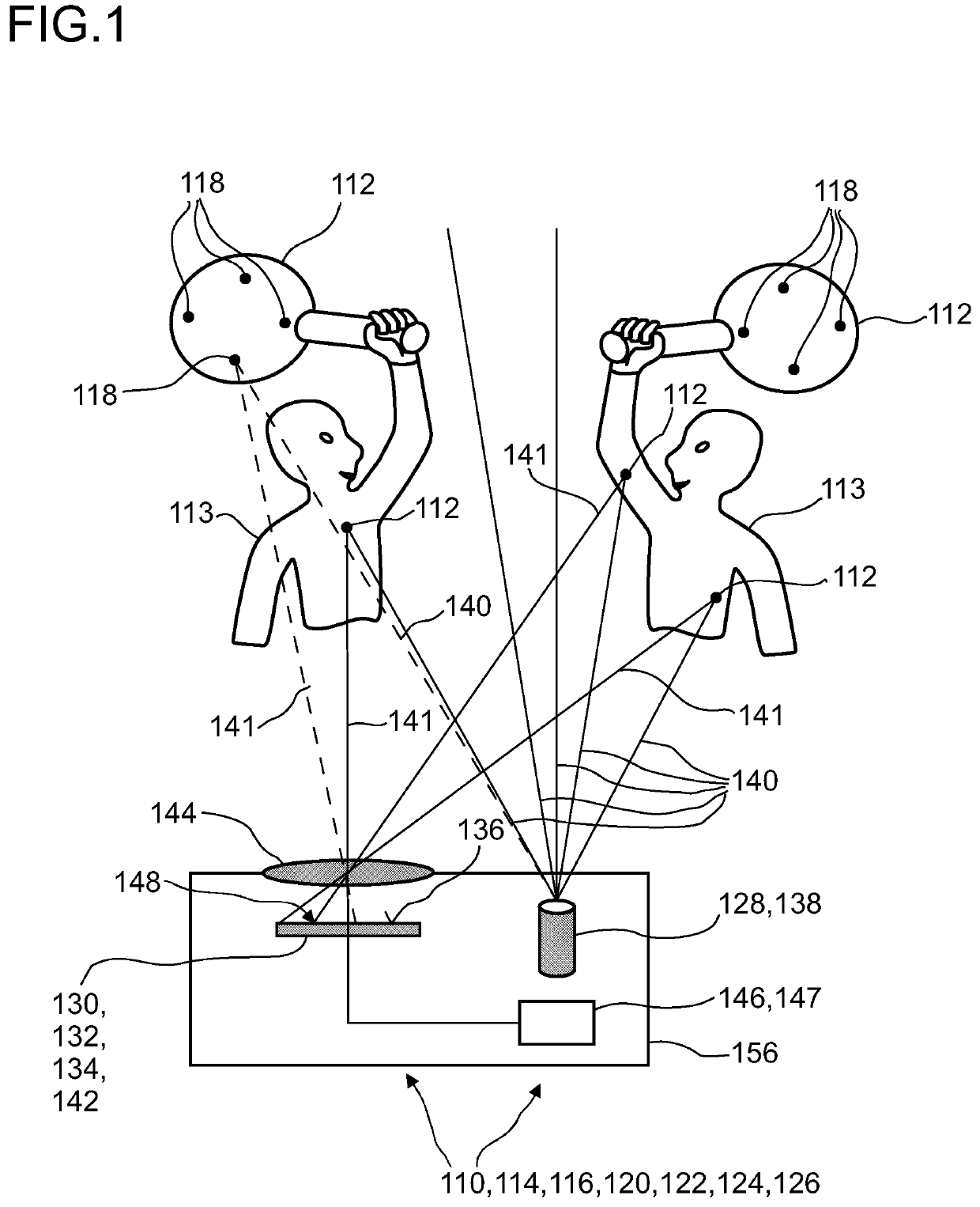
[0375]FIG. 1 shows, in a highly schematic illustration, a detector 110 for determining a position of at least one object 112. The detector 110 specifically may be embodied as a camera 114 and / or may be part of a camera 114. The camera 114 may be made for imaging, specifically for 3D imaging, and may be made for acquiring standstill images and / or image sequences such as digital video clips. Other embodiments are feasible. FIG. 1 further shows an embodiment of a detector system 116, which, besides the at least one detector 110, comprises one or more beacon devices 118, which, in this example, may be attached and / or integrated into an object 112, the position of which shall be detected by using the detector 110. FIG. 1 further shows an exemplary embodiment of a human-machine interface 120, which comprises the at least one detector system 116 and, further, an entertainment device 122, which comprises the human-machine interface 120. FIG. 1 further shows an embodiment of a tracking syste...

second embodiment

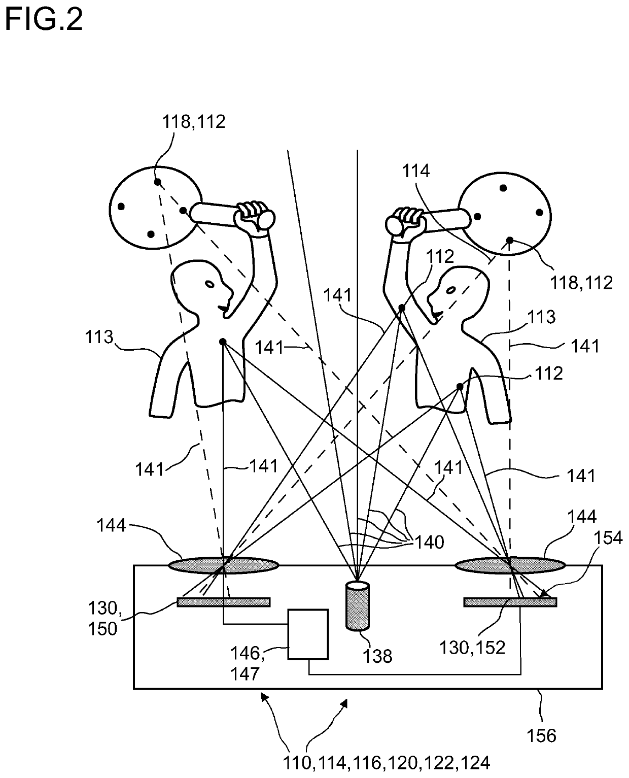
[0424]FIG. 2 shows the detector 110, detector system 116, camera 114, entertainment device 122 and tracking system 124. With respect of detector 110, detector system 116, camera 114, entertainment device 122 and tracking system 124 reference is made to the description of FIG. 1. In addition to FIG. 1, in this embodiment, the detector 110 may comprise two sensor elements 130, a first sensor element 150 and a second sensor element 152. The first sensor element 150 and the second sensor element 152 may be connected by a mechanical connector 156. The mechanical connector 156 may be adjustable and / or non-permanent. Some points may be illuminated by the optional illumination source 138 and may be detected by both sensor elements 130. The evaluation device 146 may be configured for determining the longitudinal coordinate z of the object 112 by evaluating the combined signal Q from at least two sensor signals of the first sensor element 150 and / or of the second sensor elements 152. The firs...


PUM


Abstract

A detector for determining a position of at least one object is disclosed and includes at least one sensor element having a matrix of optical sensors, the optical sensors each having a light-sensitive area. Each optical sensor is designed to generate at least one sensor signal in response to an illumination of its respective light-sensitive area by a light beam propagating from the object to the detector. The sensor element is adapted to determine at least one reflection image. The detector also includes at least one evaluation device adapted to select at least one reflection feature of the reflection image at least one first image position in the reflection image. The evaluation device is adapted to determine at least one reference feature in at least one reference image and at least one second image position in the reference image corresponding to the at least one reflection feature.

Description

FIELD OF THE INVENTION[0001]The invention relates to a detector for determining a position of at least one object, a method for determining a relative spatial constellation by using at least one detector for determining a position of at least one object and a method for calibrating at least one detector. The invention further relates to a human-machine interface for exchanging at least one item of information between a user and a machine, an entertainment device, a tracking system, a camera, a scanning system and various uses of the detector device. The devices, methods and uses according to the present invention specifically may be employed for example in various areas of daily life, gaming, traffic technology, production technology, security technology, photography such as digital photography or video photography for arts, documentation or technical purposes, medical technology or in the sciences. Further, the invention specifically may be used for scanning one or more objects and...

Claims


Application Information

Patent Timeline
Patent Type & Authority Applications(United States)
IPC IPC(8): G01S3/784G01S17/46G01S7/481G06T7/70
CPCG01S7/4817G01S17/46G06T7/70G01S3/784G01S7/481G01S11/12
Inventor SCHINDLER, PATRICKSCHILLEN, PETEREBERSPACH, MICHAELLENNARTZ, CHRISTIANSEND, ROBERTBRUDER, INGMARHENGEN, HEIKODIESSELBERG, LARS
Owner TRINAMIX GMBH
Why Eureka
Try Eureka