Surface covering system and method for producing such a system

a technology of surface covering and surface covering, which is applied in the direction of roof drainage, sustainable buildings, flooring, etc., can solve the problems of difficulty in achieving an even decline, large time consumption, and many heavy objects being lifted by builders, and achieves the effect of easy and rapid construction

Active Publication Date: 2016-04-05
GRADE GRP
View PDF16 Cites 4 Cited by
  • Summary
  • Abstract
  • Description
  • Claims
  • Application Information

AI Technical Summary

Benefits of technology

[0008]An object of the present invention is to provide a surface covering system including prefabricated building elements, with which a surface can easily and quickly be constructed having a sufficient drainage of water and an even decline towards a draining sewer.

Problems solved by technology

This method has a number of disadvantages, including great time consumption, lifting of many heavy objects by the builder and difficulties in achieving an even decline.
There will often be uneven places and inverse declines somewhere on the floor, giving rise to water puddles.
It also becomes unnecessarily difficult to put floor clinkers on the filler treated floor, because the clinkers must be cut in order to give even joints.
These edges complicate the laying of clinkers on the floor and are uncomfortable to stand on.
This cutting is time consuming, and there will be a great deal of waste that must be disposed of.

Method used


Image

  • Surface covering system and method for producing such a system
  • Surface covering system and method for producing such a system
  • Surface covering system and method for producing such a system

Examples


Embodiment Construction

[0051]In the following, a detailed description of embodiments of the invention is given. All examples are to be considered parts of the general description, and they are thus in general possible to combine.

[0052]The surface covering system will be described below as a floor system for a wet room, but it is of course possible to use the system to create drainage on other substantially flat, delimited surfaces, for instance on roofs or inner yards.

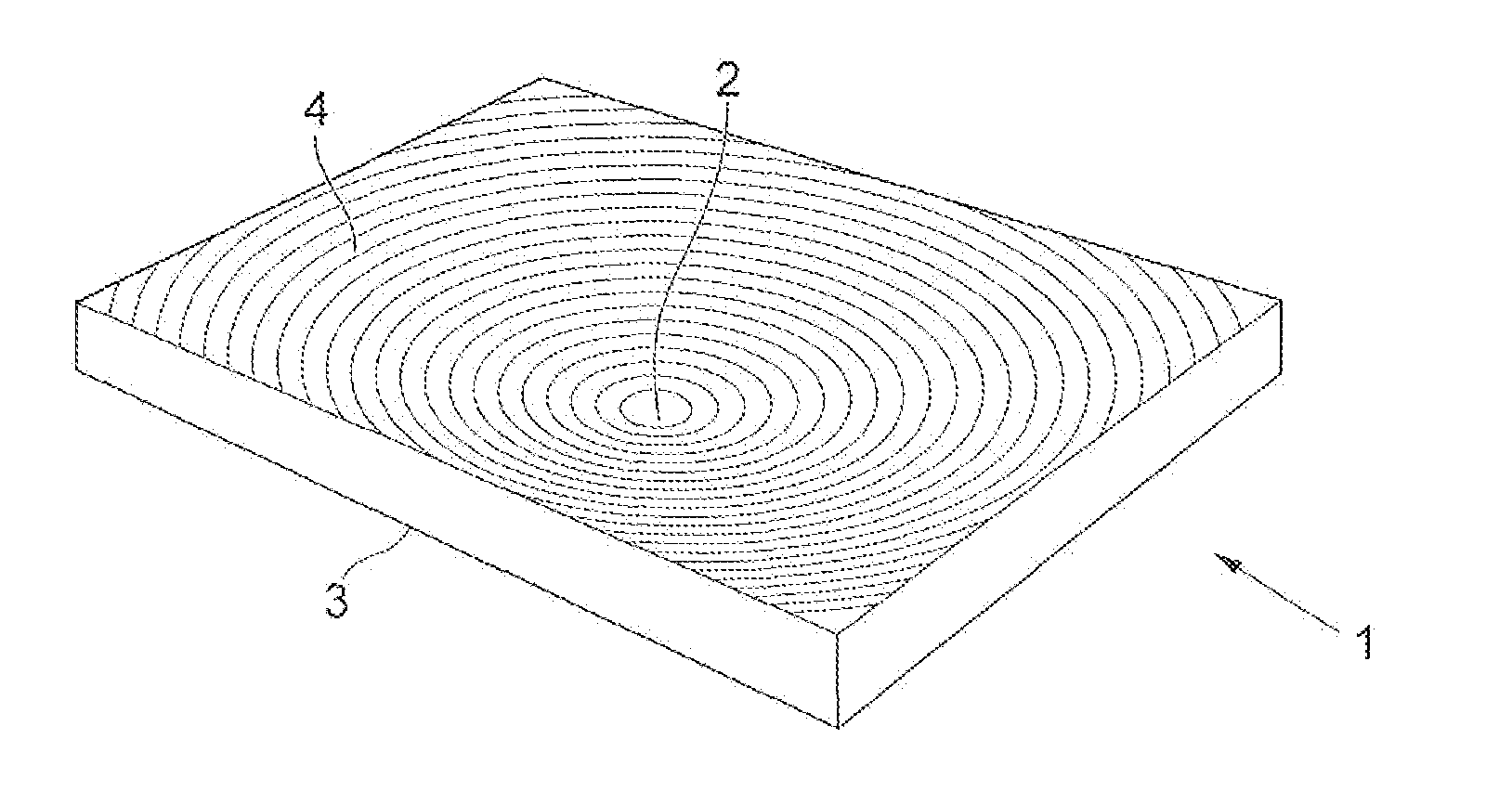
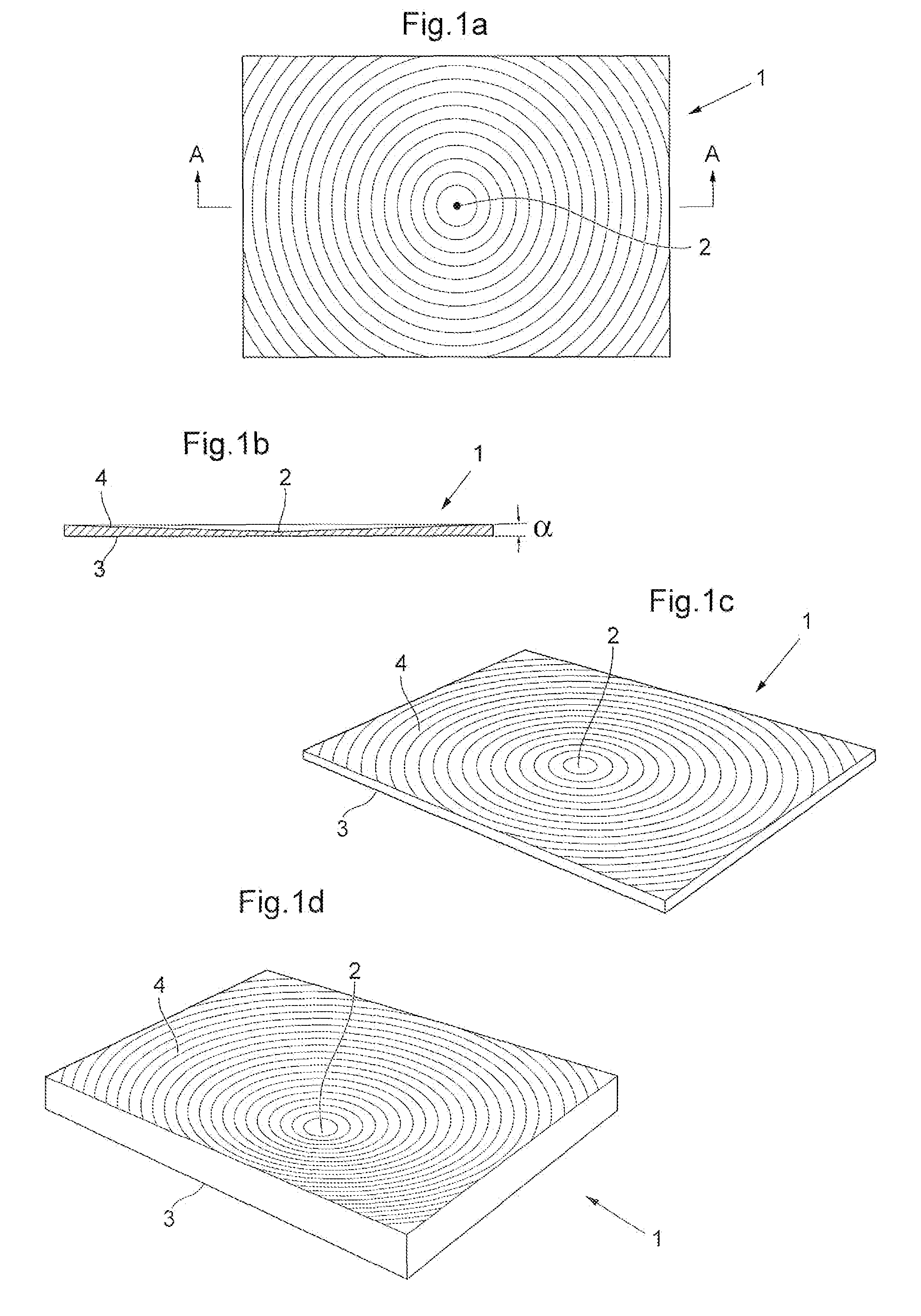
[0053]FIGS. 1a-1c show a first embodiment of the floor system, which comprises a plate 1 with a mark 2 for a drainage point in the form of a floor drain. The mark 2 may also be the drainage point / floor drain as such. The mark 2 is in this embodiment centred on the plate 1, but it may also be placed at another suitable place away from the edge of the plate, e.g. 450 mm to 600 mm in on the plate. The plate is in this embodiment rectangular, but it may also be substantially rectangular (for instance square), triangular, quadrangular or have ano...


PUM


Abstract

The invention relates to a surface covering system intended for a surface in the form of a wet room floor, a roof or another substantially flat, delimited surface which is exposed to water and needs drainage, and to methods for preparing such a system. The surface covering system comprises at least one plate with a mark showing a drainage point and a substantially flat lower surface and an upper surface with a first decline towards the mark. The invention is characterized by that the first decline is circular and has a radial slope (α) directed towards the mark from every point on the at least one plate. The decline creates a cavity in the plate in the shape of at least a part of a blunt virtual cone with the apex of the cone directed towards the mark, achieving a modular surface covering system with an even circular decline.

Description

[0001]This application is a continuation of PCT Application No. PCT / SE2013 / 050544, filed May 15, 2013, which claims priority of SE 1350095-4, filed Jan. 29, 2013, and SE 1250734-9, filed Jun. 29, 2012, and SE 1250504-6 May 16, 2012, the entire contents of each of which are hereby incorporated by reference.BACKGROUND[0002]The present invention relates generally to a surface covering system intended for covering a floor, a roof or another substantially flat, delimited surface which may be exposed to a falling fluid and thus needs drainage. The system comprises plates with a prefabricated decline towards a draining sewer. The invention also relates to methods for preparing such a system.[0003]In order for water or other fluid, such as oil and similar, not to collect on a surface, a decline towards a draining sewer is needed. The surface may for example be a support in the form of a flat roof, the ground surface on an inner yard, the floor in a garage, a kitchen or a wet room, such as a...

Claims


Application Information

Patent Timeline
Patent Type & Authority Patents(United States)
IPC IPC(8): E04F15/00E04D13/04E04D3/24E04B5/00E04B5/02E04F15/02E04F15/18A47K3/40E04F15/08
CPCE04F15/02188E04B5/02E04C1/24E04D3/24E04D13/0481E04F15/182A47K3/40E04F15/08E04F2203/02E04F2290/023E04D13/1693Y02B30/00E04F15/02183
Inventor SJODEN, TORDBOART, ULFGUSTAVSON, MORTEN
Owner GRADE GRP
Why Eureka
Try Eureka